Pump for distributing liquid product and dispenser comprising such a pump

A technology for fluid products, dispensing pumps, applied in a single hand-held device, spray device, etc., to solve problems such as unfavorable gaskets

Active Publication Date: 2010-01-20
APTAR FRANCE SAS
View PDF3 Cites 2 Cited by
  • Summary
  • Abstract
  • Description
  • Claims
  • Application Information

AI Technical Summary

Problems solved by technology

This gasket may be disadvantageous in terms of complexity of pump as...

Method used


Image

  • Pump for distributing liquid product and dispenser comprising such a pump
  • Pump for distributing liquid product and dispenser comprising such a pump
  • Pump for distributing liquid product and dispenser comprising such a pump

Examples


Embodiment Construction

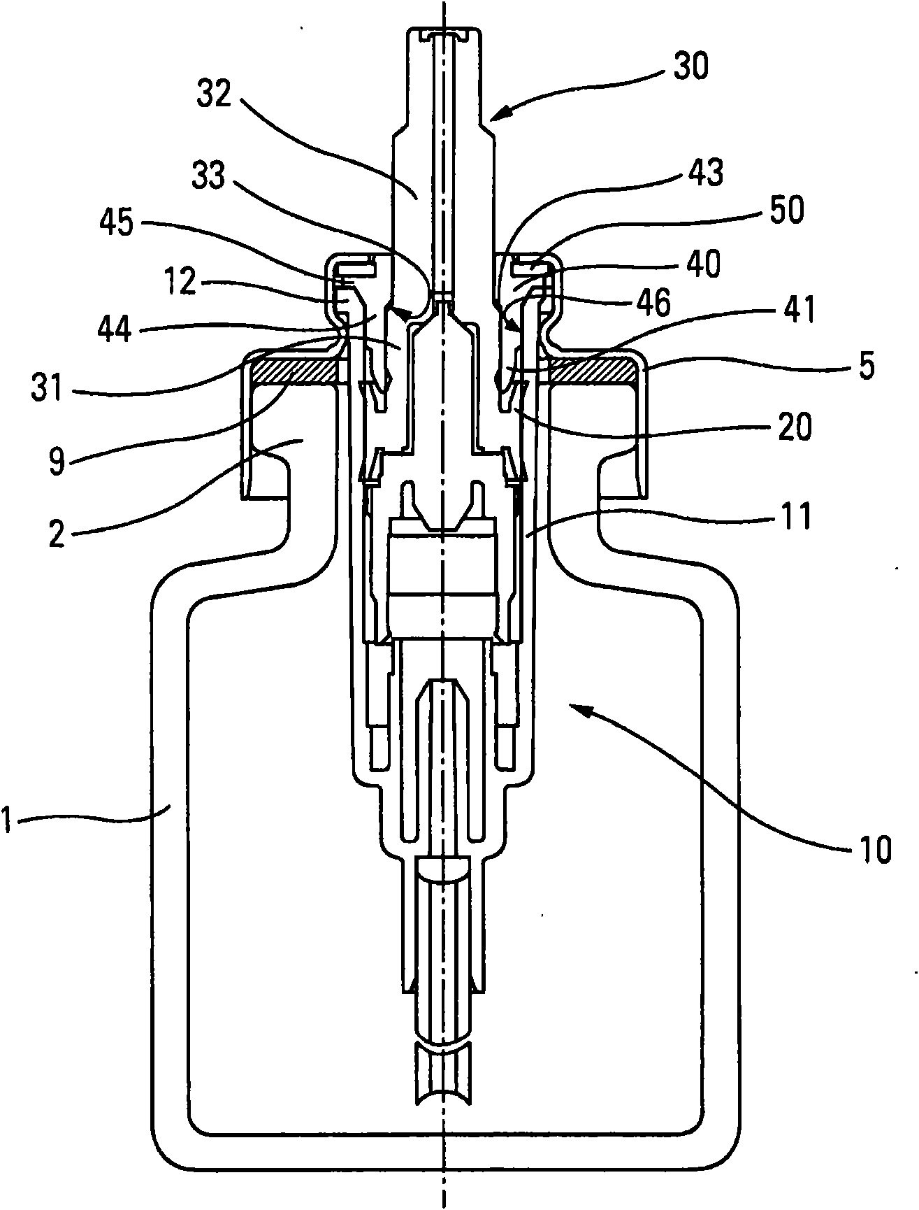
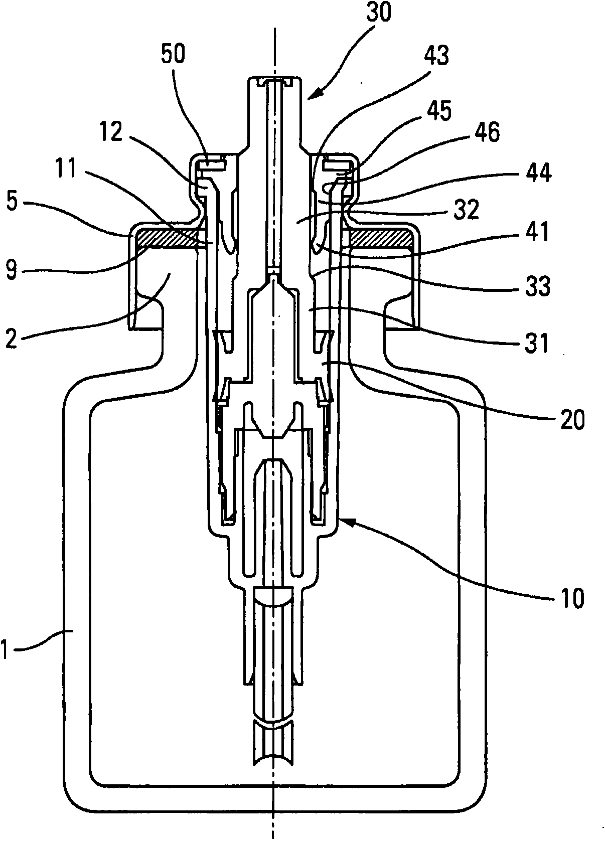
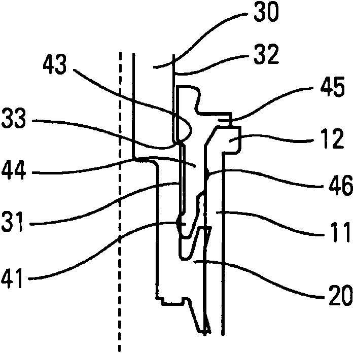
[0025] refer to figure 1 and 2 , shows a fluid dispensing device according to an advantageous embodiment of the present invention. The device has a container 1 with a neck 2 in which a pump 10 is assembled by means of a retaining ring 5 and preferably inserted with a sealing gasket 9 called a neck gasket. The pump has a pump body 11 with an upper edge 12 . A piston 20 slides in a sealed manner inside said pump body 11 at each actuation in order to dispense a dose of product from the container 1 . The internal structure of the pump will not be described in further detail below, since the invention is applicable to all types of pumps and is in no way subject to figure 1 , 2 The limitations of the specific characteristics of the pump are given as examples. In conventional manner, as shown in the figures, the piston 20 is connected, in particular integral, with an actuating lever 30, on which a dispensing head or button (not shown) is assembled, in order to enable The pump i...


PUM


Abstract

Fluid product dispensing pump (10), comprising a pump body (11), a piston (20) sliding sealingly in said pump body (11) between an inactive position and an actuating position, said piston (20) being connected to an actuating rod (30) axially extending out of the said pump body (11), a ferrule (40) defining the inactive position of the said piston (20), said ferrule (40) sealingly connected to the actuating rod (30) when the actuating rod (30) moves from the inactive position and an intermediary position, and said ferrule (40) sealingly connected with the actuating rod (30) when the actuating rod (30) moves between the said intermediary position and the actuating position, so as to allow air venting of the pump (10).

Description

technical field [0001] The present invention relates to a fluid dispensing pump and a dispenser having such a pump. Background technique [0002] Fluid dispensing pumps are well known in the art. It is of different kinds, especially pneumatic pumps, in which the negative pressure generated in the container by the dispensing of a dose of product is compensated by the circulation air entering the device from the outside. In such pumps, there is usually a sleeve (virole) which fits inside the pump body and cooperates sealingly with the piston in the stop position, on the one hand to limit the stop position of the piston and on the other hand to close the pump in a sealed manner, Any risk of leakage is thus avoided, for example when the device on which the pump is mounted is stored in an inverted position with the pump underneath the container. This static seal between the bushing and the piston is very fragile since it usually consists of only an annular contact between the i...

Claims


Application Information

Patent Timeline
IPC IPC(8): B05B11/00
CPCB05B11/305B05B11/3018B05B11/0016B05B11/0044B05B11/1018B05B11/105
Inventor F·勒马纳
Owner APTAR FRANCE SAS
Why Eureka
Try Eureka