Sliding mechanism

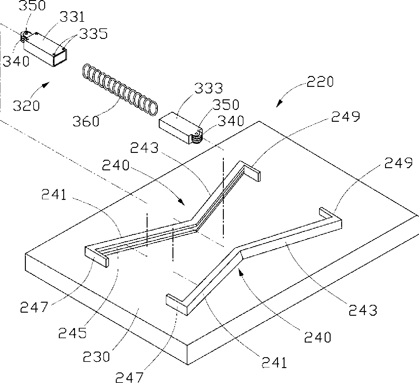
A sliding mechanism and sliding cover technology are applied in the directions of telephone structure, support structure installation, casing/cabinet/drawer parts, etc., which can solve problems such as affecting the service life, wearing of related components, and hindering the sliding of the connecting assembly 320. , to achieve the effect of prolonging the service life and reducing the sliding friction resistance

Inactive Publication Date: 2009-06-17
HONG FU JIN PRECISION IND (SHENZHEN) CO LTD +1
View PDF0 Cites 5 Cited by
  • Summary
  • Abstract
  • Description
  • Claims
  • Application Information

AI Technical Summary

Problems solved by technology

[0008] In the above-mentioned sliding mechanism, there is a large friction force between the roller 340 and the guide rail 245, which will hinder the sliding of the connecting assembly 320 relative to the guide member 220, and the friction will easily cause wear of the relevant components and affect its service life.

Method used


Image

  • Sliding mechanism
  • Sliding mechanism
  • Sliding mechanism

Examples


Embodiment Construction

[0017] The sliding mechanism of the present invention will be further described in detail with reference to the accompanying drawings and embodiments.

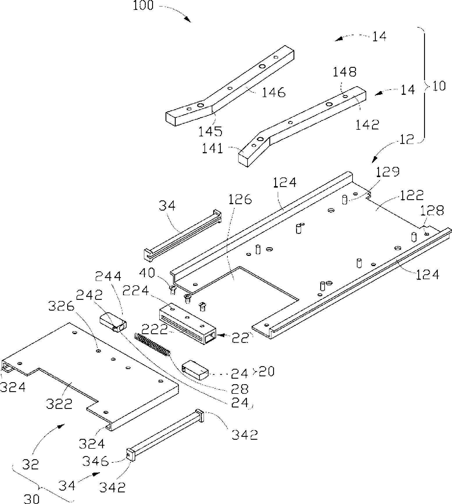
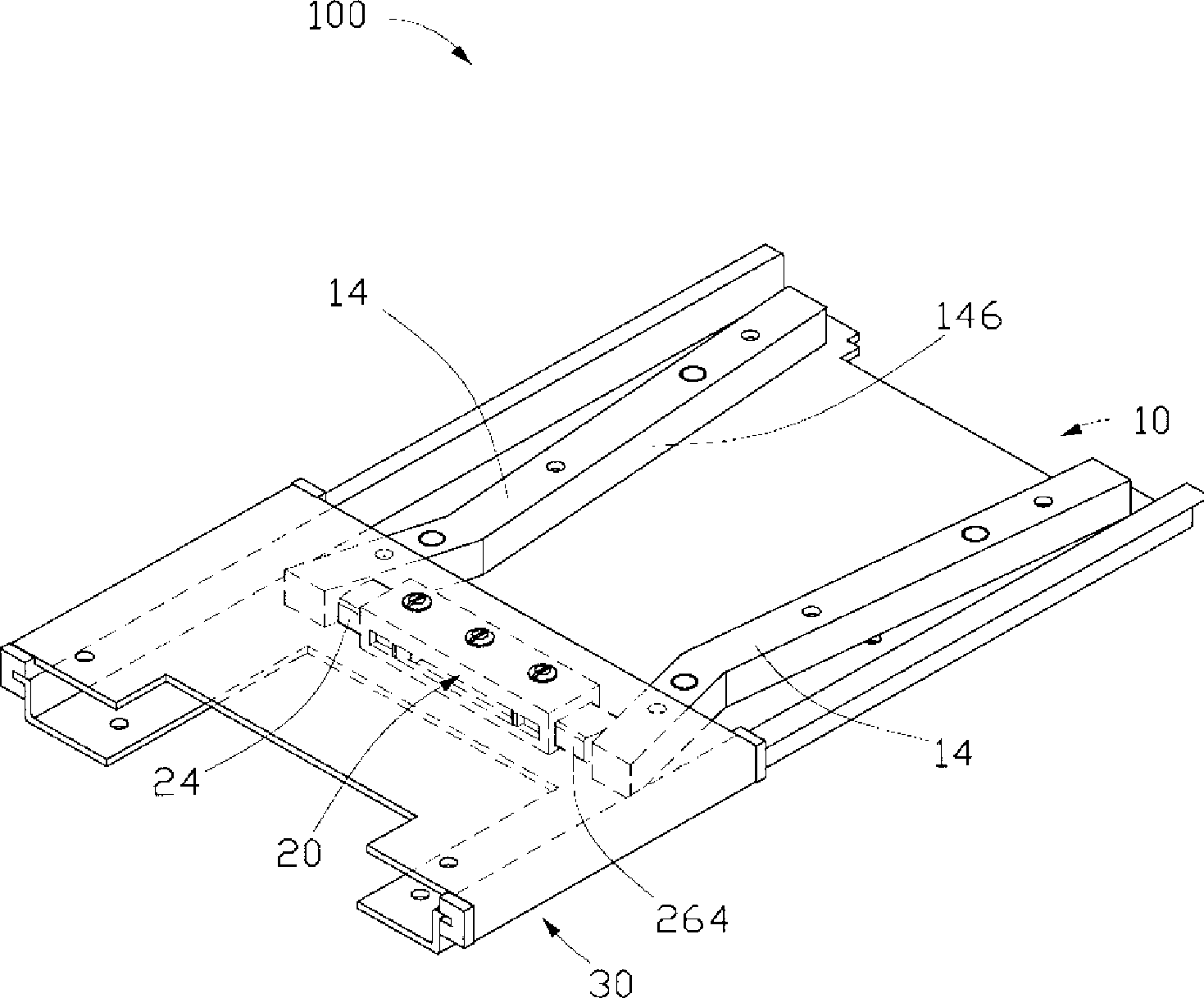
[0018] see figure 2 , the sliding mechanism 100 of the first preferred embodiment of the present invention includes a back plate assembly 10 , a connecting assembly 20 and a sliding assembly 30 .

[0019] The backplane assembly 10 includes a backplane 12 and two guide rails 14 mounted on the backplane 12 .

[0020] The backboard 12 is substantially a rectangular board, which includes a bottom board 122 and two raised sides 124 . The two protruding sides 124 are formed by bending and protruding slightly from two opposite sides of the bottom plate 122 towards the same side of the bottom plate 122 . One end of the bottom plate 122 is provided with a square gap 126, and the bottom plate 122 is also provided with a number of round holes 128 for connecting the back plate 12 to the body with buttons in the electronic device. In ad...


PUM


Abstract

A sliding mechanism comprises a sliding assembly which can relatively slide, a back board assembly and a connection assembly, wherein the sliding assembly comprises a slide cover, the back board assembly comprises a back board and two guide rails which are relatively fixed on the back board, wherein the two guide rail have at least a group of inflexions which are relatively arranged, the connection assembly is connected with the slide cover, and matched with the two guide rails to enable the sliding assembly to semi-automatically slide relative to the back board assembly, the connection assembly comprises two slide blocks matched with the guide rails, wherein the two slide blocks can relatively slide to close or move away, and at least acting force which makes the two slide blocks mutually exclusive exists between the two slide blocks in the sliding process, both the slide block and the guide rail have magnet, and one end of the slide block adjacent to the guide rail has the same magnetic polarity as the inner side of the guide rail. The sliding mechanism of the invention has the advantages of effectively reducing sliding-frictional resistance and extending the service life of the sliding mechanism.

Description

technical field [0001] The invention relates to a sliding mechanism, in particular to a sliding mechanism used in portable electronic devices such as mobile phones, game machines and palmtop computers. Background technique [0002] In recent years, portable electronic devices have become more and more popular, and sliding portable electronic devices are favored and loved by consumers. [0003] Current slide-type portable electronic devices are mainly classified into three categories. One type adopts a manual sliding mechanism, that is, the user moves the sliding cover manually through the whole process. There is also a semi-automatic sliding mechanism. The user only needs to push the sliding cover to a certain distance, and the sliding cover will automatically move and locate to a fully closed state or a fully open state. The other type adopts a fully automatic sliding mechanism, and the user can realize the automatic movement of the sliding mechanism in the whole process ...

Claims


Application Information

Patent Timeline
Patent Type & Authority Applications(China)
IPC IPC(8): H05K5/02H05K7/14H04M1/02
CPCH04M1/0237
Inventor 阮向东
Owner HONG FU JIN PRECISION IND (SHENZHEN) CO LTD
Why Eureka
Try Eureka