Wire harness

Active Publication Date: 2015-12-31
YAZAKI CORP
View PDF2 Cites 4 Cited by
  • Summary
  • Abstract
  • Description
  • Claims
  • Application Information

AI Technical Summary

Benefits of technology

[0015]According to the present invention having the above features, the wire harness is a long one whose electrical pathways have a long insertion distance, and when the present invention is adopted in the long wire harness, the operat

Problems solved by technology

At this time, there is a problem which is that if the sliding friction

Method used


Image

  • Wire harness
  • Wire harness
  • Wire harness

Examples


Embodiment Construction

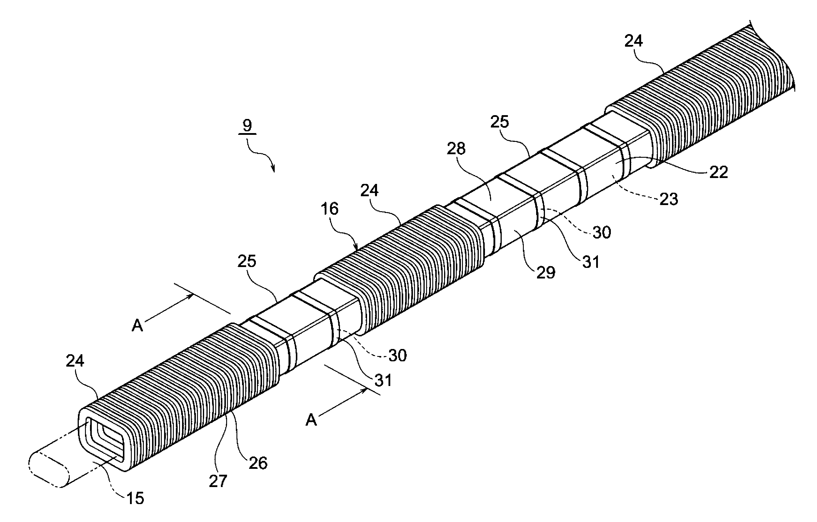
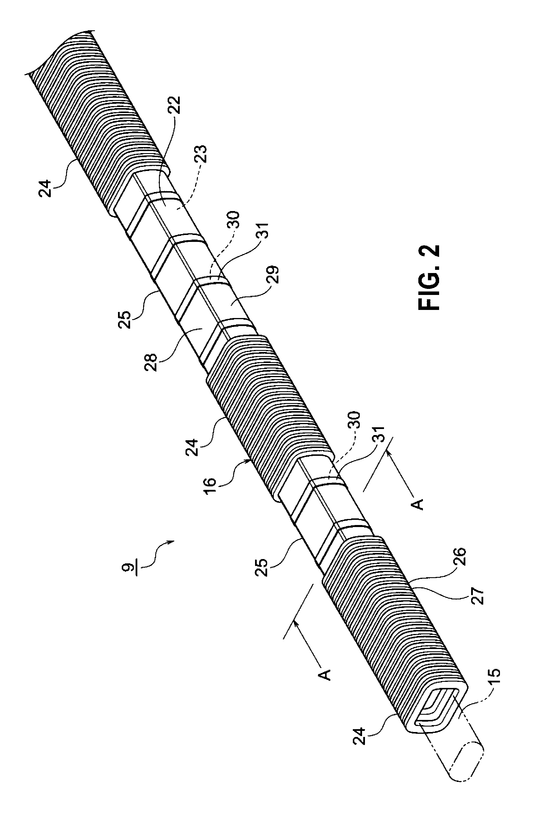
[0023]A wire harness includes a pipe-like exterior member whose inner surface is formed with recesses, and one or a plurality of electrical pathways which are inserted through the exterior member. Curved surfaces or tapers are formed at edges of the recesses.

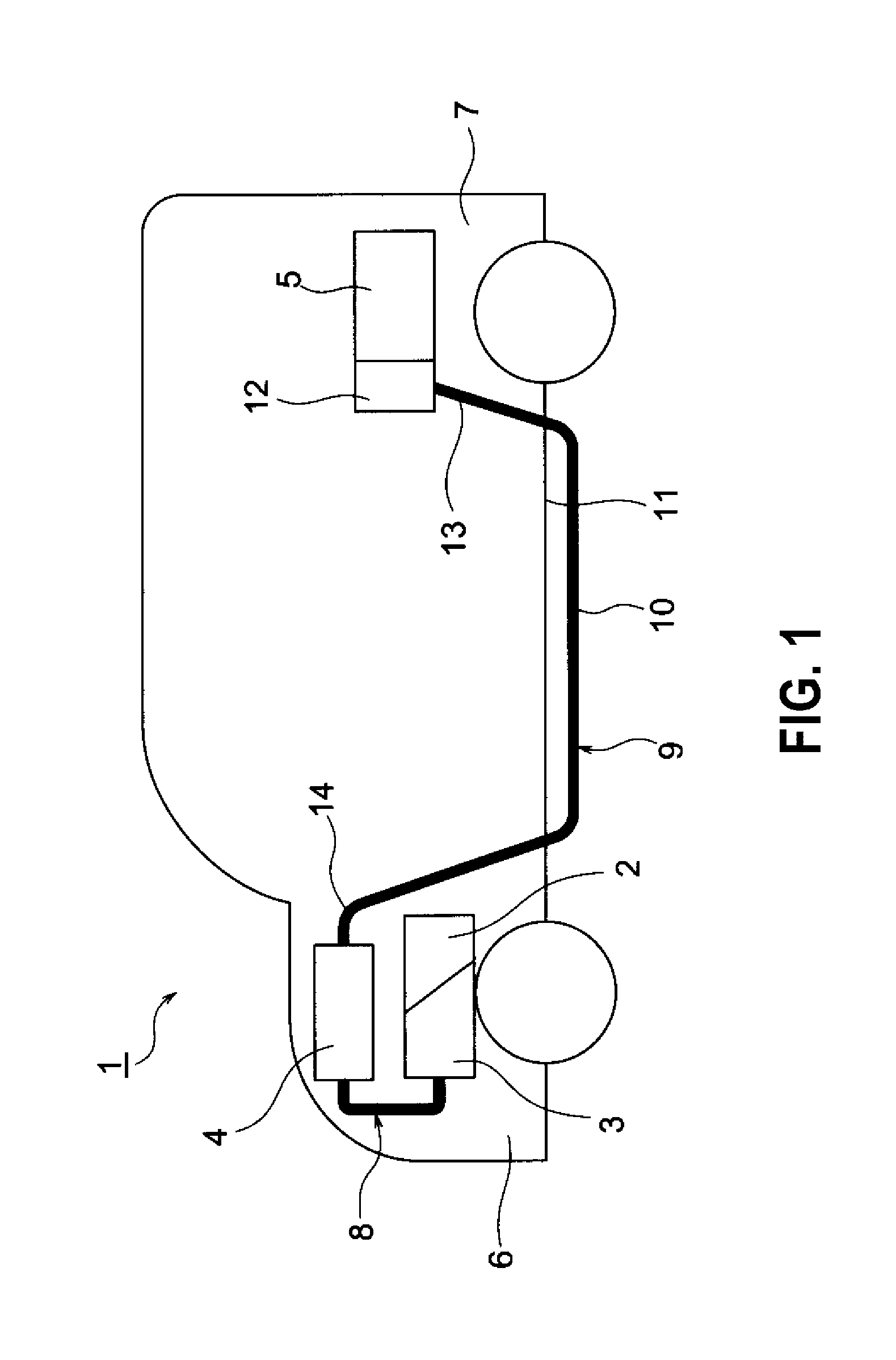
[0024]Below, embodiments will be described with reference to the figures. FIG. 1 is a schematic view which indicates that a wire harness of the present invention is wired. FIG. 2 is a perspective view of the wire harness of an embodiment of the present invention. FIG. 3 is an A-A line sectional view of FIG. 2. FIG. 4 is a sectional view when an electrical pathway is inserted in the wire harness of the embodiment of the present invention. FIG. 5 is a perspective view of a wire harness as a variation of the embodiment of the present invention. FIG. 6 is a B-B line sectional view of FIG. 5.

[0025]In the present embodiment, the present invention is applied to a wire harness which is wired in a hybrid vehicle (or an electric vehicle o...


PUM


Abstract

A wire harness includes an electrical pathway and a pipe like exterior member that covers the electrical pathway. The exterior member includes a low rigidity portion which is flelxible and a high rigidity portion which is unflexible and has a rigidity higher than the low rigidity portion, and the low rigidity portion and the high rigidity portion are successively arranged in an extending direction of the electrical pathway.

Description

CROSS REFERENCE TO RELATED APPLICATIONS[0001]This application is a continuation of PCT application No. PCT / JP2014 / 055757, which was filed on Mar. 6, 2014 based on Japanese Patent Application (No. 2013-043653) filed on Mar. 6, 2013, the contents of which are incorporated herein by reference.BACKGROUND OF THE INVENTION[0002]1. Technical Field[0003]The present invention relates to a wire harness that includes a pipe-like exterior member, and one or a plurality of electrical pathways that are inserted through the exterior member.[0004]2. Related Art[0005]Wire harnesses are used as members that are electrically connected between high voltage devices in a hybrid vehicle or an electric vehicle.[0006]A wire harness disclosed in JP-A-2004-224156 includes a plurality of high voltage electric wires (electrical pathways) and a plurality of metal pipes which accommodates the high voltage electric wires respectively. The wire harness is a long member that extends from the front portion of the veh...

Claims


Application Information

Patent Timeline
IPC IPC(8): B60R16/02H02G3/04
CPCB60R16/0215H02G3/0462H02G3/0487H02G3/0468
Inventor OGUE, TAKESHIADACHI, HIDEOMIINAO, SHINICHIOGA, TATSUYAYOSHIDA, HIROYUKISUGURO, MASAAKI
Owner YAZAKI CORP
Why Eureka
Try Eureka