Supercharge Your Innovation With Domain-Expert AI Agents!

System and method for controlled expansion valve adjustment

A technology for expansion valves and refrigeration systems, applied in the direction of refrigeration safety arrangements, gas cycle refrigerators, refrigerators, etc., can solve the problems that the flow adjustment device cannot operate normally, and it is difficult to control the pull-down process, etc.

Inactive Publication Date: 2009-06-17
CARRIER CORP
View PDF0 Cites 7 Cited by
  • Summary
  • Abstract
  • Description
  • Claims
  • Application Information

AI Technical Summary

Problems solved by technology

When the evaporator temperature is supercritical, there is no "superheat" and therefore, the flow regulator cannot function properly
As a result, it is difficult to control the initial pull-down process necessary to bring the refrigerated zone to the desired set point temperature and return the refrigerant to the normal subcritical process

Method used


Image

  • System and method for controlled expansion valve adjustment
  • System and method for controlled expansion valve adjustment
  • System and method for controlled expansion valve adjustment

Examples


Embodiment Construction

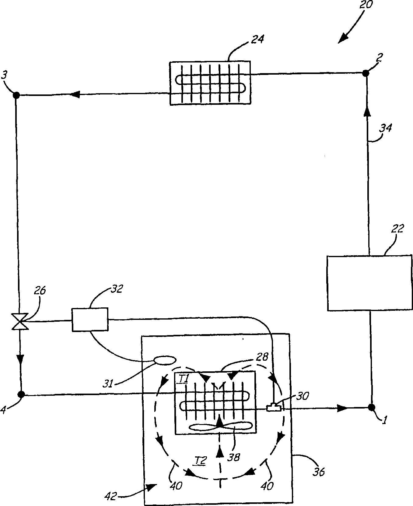
[0012] figure 1 A schematic diagram of a refrigeration system 20 including a compressor 22 , a gas cooler 24 , an expansion valve 26 , an evaporator 28 , an evaporator sensor 30 , an enclosure sensor 31 , and a valve controller 32 is shown. Compressor 22 may comprise any type of compressor including (but not limited to): reciprocating, scroll, screw, rotary vane, vertical vane, variable speed, hermetic, and open drive compressors.

[0013] The refrigeration system 20 is suitable for any occasion requiring a cold source, such as in temperature control units of buildings and automobiles. However, the refrigeration system 20 will be described generically in terms of "enclosures" that require cooling. For example, this "enclosure" might be an office area in a building, or a food storage area in a refrigerated food transport vehicle.

[0014] Such as figure 1 As shown, the refrigerant path 34 is formed by connecting various components in the refrigeration system 20 . The refrig...


PUM


Abstract

A method for controlling temperature pulldown of an enclosure with a refrigeration system having a compressor, a heat rejecting heat exchanger, an expansion valve, and an evaporator comprises circulating a refrigerant through the refrigeration system, sensing a parameter of the enclosure, determining a desired evaporator pressure based upon the parameter sensed, and adjusting the expansion valve as a function of the desired evaporator pressure.

Description

technical field [0001] The present invention relates generally to refrigeration systems. More specifically, the present invention relates to transcritical refrigeration systems configured to improve temperature pull-down after system start-up. Background technique [0002] In a typical refrigeration system using a circulating refrigerant, the refrigerant is circulated through a specific zone being refrigerated to remove heat from that zone. The refrigerant enters the evaporator as a liquid or a saturated mixture of liquid and vapor, which is evaporated (ie, evaporated into pure vapor) by absorbing heat from the area being refrigerated. This process occurs at a refrigerant temperature slightly lower than that of the region being refrigerated in order to facilitate heat transfer from the region to the refrigerant. The flow of refrigerant through the evaporator is typically adjusted to maintain the temperature of the vapor leaving the evaporator by a fixed margin or "superhea...

Claims


Application Information

Patent Timeline
Patent Type & Authority Applications(China)
IPC IPC(8): F25B41/04
CPCF25B49/02F25B9/008F25B2600/2513F25B2700/197F25B2700/21175F25B2309/061F25B2700/2104
Inventor J·W·布什W·P·比格尔B·米特拉
Owner CARRIER CORP
Features
  • R&D
  • Intellectual Property
  • Life Sciences
  • Materials
  • Tech Scout
  • Unparalleled Data Quality
  • Higher Quality Content
  • 60% Fewer Hallucinations
Learn More