Estimating evaporator airflow in vapor compression cycle cooling equipment

Active Publication Date: 2005-12-13
FILED DIAGNOSTICS SERVICES INC
View PDF48 Cites 118 Cited by
  • Summary
  • Abstract
  • Description
  • Claims
  • Application Information

AI Technical Summary

Benefits of technology

[0009]The present invention is intended for use with any manufacturer's HVAC&R equipment. The present invention, when implemented in hardware/firmware, is relatively inexpensive and does not strongly depend on the skill or

Problems solved by technology

For example, problems such as undersized ducts, dirty filters, or a dirty evaporator coil cause low airflow.
Low evaporator airflow reduces the capacity and efficiency of the air conditioner and may, in extreme cases, risk freezing the evaporator coil, which could lead to compressor failure due to liquid refrigerant floodback.
On the other hand, if the airflow is too high, the evaporator coil will not be able to do an adequate job of dehumidification, resulting in lack of c

Method used


Image

  • Estimating evaporator airflow in vapor compression cycle cooling equipment
  • Estimating evaporator airflow in vapor compression cycle cooling equipment
  • Estimating evaporator airflow in vapor compression cycle cooling equipment

Examples


Embodiment Construction

[0016]In describing preferred embodiments of the invention, specific terminology has been selected for clarity. However, the invention is not intended to be limited to the specific terms so selected, and it is to be understood that each specific term includes all technical equivalents that operate in a similar manner to accomplish a similar purpose.

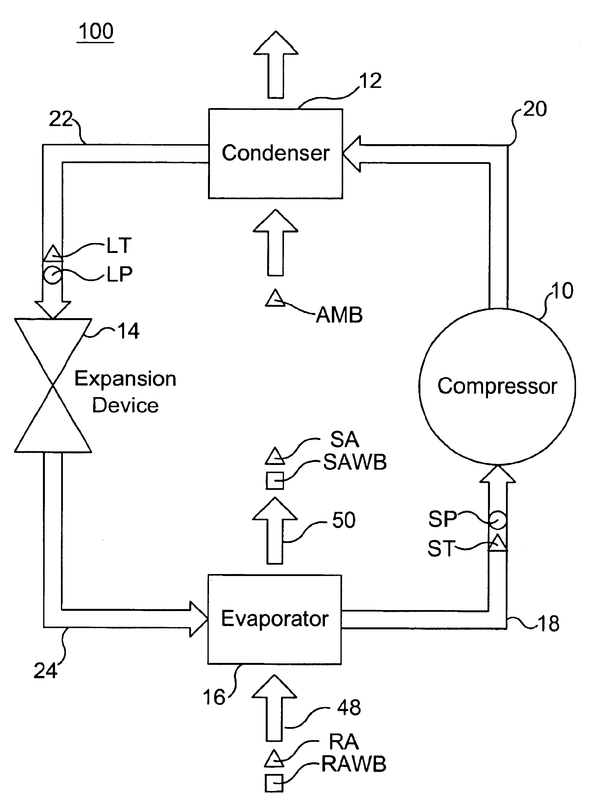
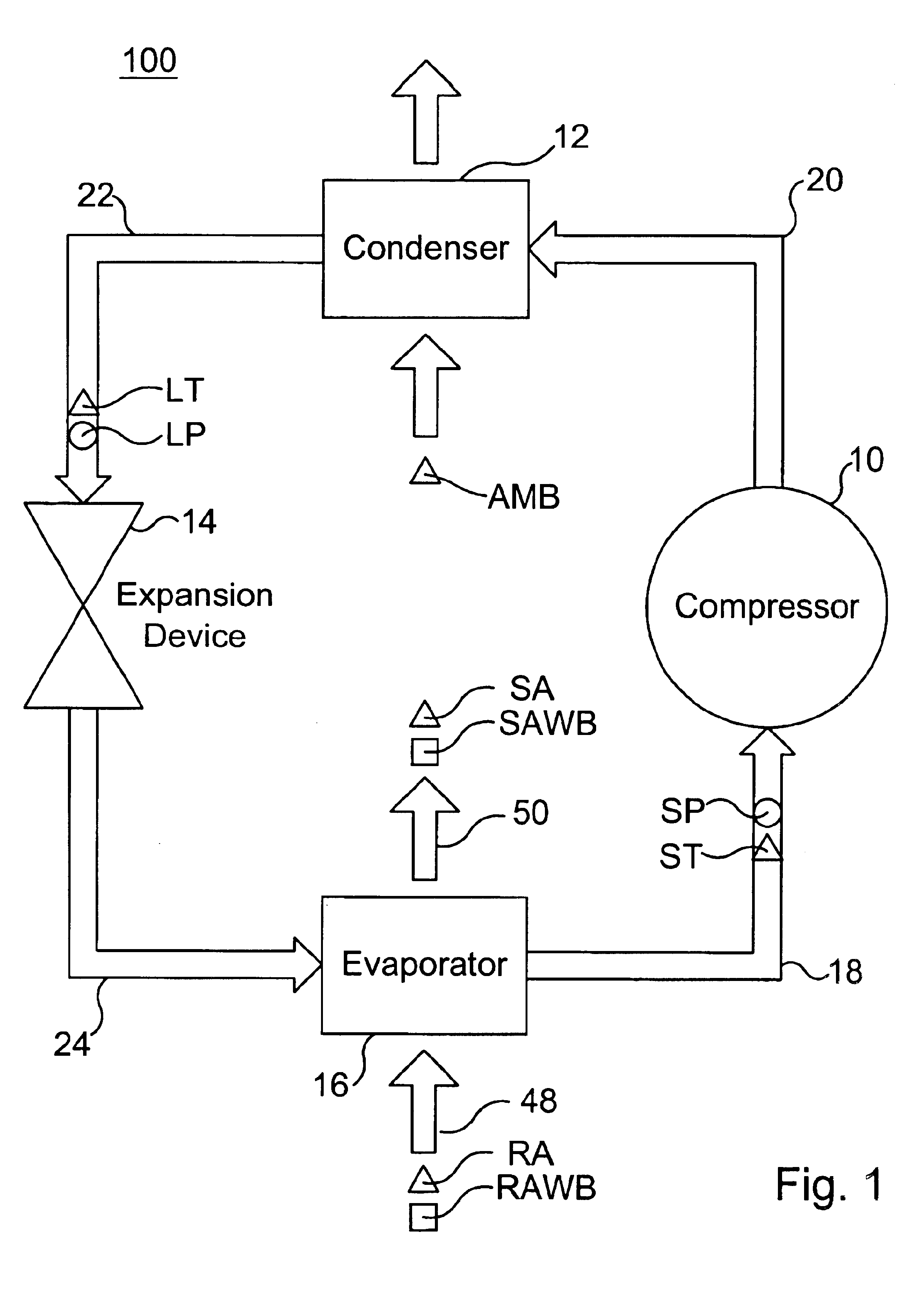
[0017]The vapor compression cycle is the principle upon which conventional air conditioning systems, heat pumps, and refrigeration systems are able to cool (or heat, for heat pumps) and dehumidify air in a defined volume (e.g., a living space, an interior of a vehicle, a freezer, etc.).

[0018]The vapor-compression cycle is made possible because the refrigerant is a fluid that exhibits specific properties when it is placed under varying pressures and temperatures.

[0019]A typical vapor compression cycle system 100 is illustrated in FIG. 1. The system is a closed loop system and includes a compressor 10, a condenser 12, an expansion device 14...


PUM


Abstract

A method for determining airflow through an evaporator coil in a vapor compression cycle by measuring the moist air conditions entering and leaving the coil, and various temperatures and pressures in the refrigerant of the vapor compression cycle. The mass airflow rate and the volumetric airflow rate are then determined.

Description

CROSS REFERENCE TO RELATED APPLICATIONS[0001]The present application claims the benefits under 35 U.S.C. §119(e) of U.S. Provisional Application No. 60 / 394,509 filed Jul. 8, 2002, titled ESTIMATING EVAPORATOR AIRFLOW IN VAPOR COMPRESSION CYCLE EQUIPMENT in the name of Todd M. Rossi, Jonathan D. Douglas and Marcus V. A. Bianchi.[0002]U.S. Provisional Application No. 60 / 394,509, filed Jul. 8, 2002, is hereby incorporated by reference as if fully set forth herein.FIELD OF THE INVENTION[0003]The present invention generally relates to the science of psychrometry and to heating, ventilating, air conditioning, and refrigeration (HVAC&R). More specifically, the invention relates to the use of psychrometric measurements, refrigerant temperature and pressure measurements in association with compressor performance equations to calculate the airflow rate through an evaporator in cooling equipment running a vapor compression cycle.BACKGROUND OF THE INVENTION[0004]The most common technology used ...

Claims


Application Information

Patent Timeline
IPC IPC(8): F25B49/02
CPCF25B49/02F25B2500/19F25B2700/13F25B2700/1933F25B2700/195F25B2700/2106F25B2700/21151F25B2700/21163F25B2700/21172F25B2700/21173
Inventor DOUGLAS, JONATHAN D.BIANCHI, MARCUS V. A.ROSSI, TODD M.
Owner FILED DIAGNOSTICS SERVICES INC
Why Eureka
Try Eureka