Motor stator and mold motor

A motor and stator technology, applied in the field of molded motors, can solve problems such as trouble

Active Publication Date: 2009-06-17
PANASONIC CORP
View PDF3 Cites 23 Cited by
  • Summary
  • Abstract
  • Description
  • Claims
  • Application Information

AI Technical Summary

Problems solved by technology

Therefore, before winding the second phase coil, it is necessary to carry out insulation treatment such as sticking an insulating tape on the connection line between the first phase coil 60 and the first phase, which is very troublesome.

Method used


Image

  • Motor stator and mold motor
  • Motor stator and mold motor
  • Motor stator and mold motor

Examples


Embodiment Construction

[0024] Embodiments of the present invention will be described below using the drawings.

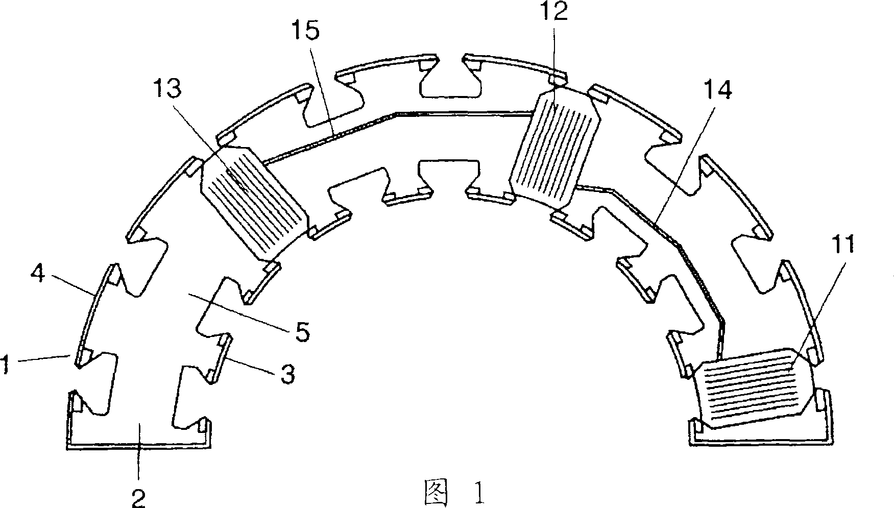
[0025] As shown in FIG. 1 , a divided stator core (hereinafter referred to as “stator core”) 1 which divides an annular stator core into half has inner teeth 3 and outer teeth 4 on both sides of a yoke 2 . The insulating cover 5 covers the stator core 1 . Hereinafter, a procedure for sequentially winding the coils of the first phase, the second phase, and the third phase of the three-phase winding into the slots between the teeth of the stator core 1 in a circular manner will be described.

[0026] First, as shown in FIG. 1 , the coils 11 , 12 , 13 of the first phase are sequentially wound on the stator core 1 via the connecting wires 14 , 15 between the connecting coils.

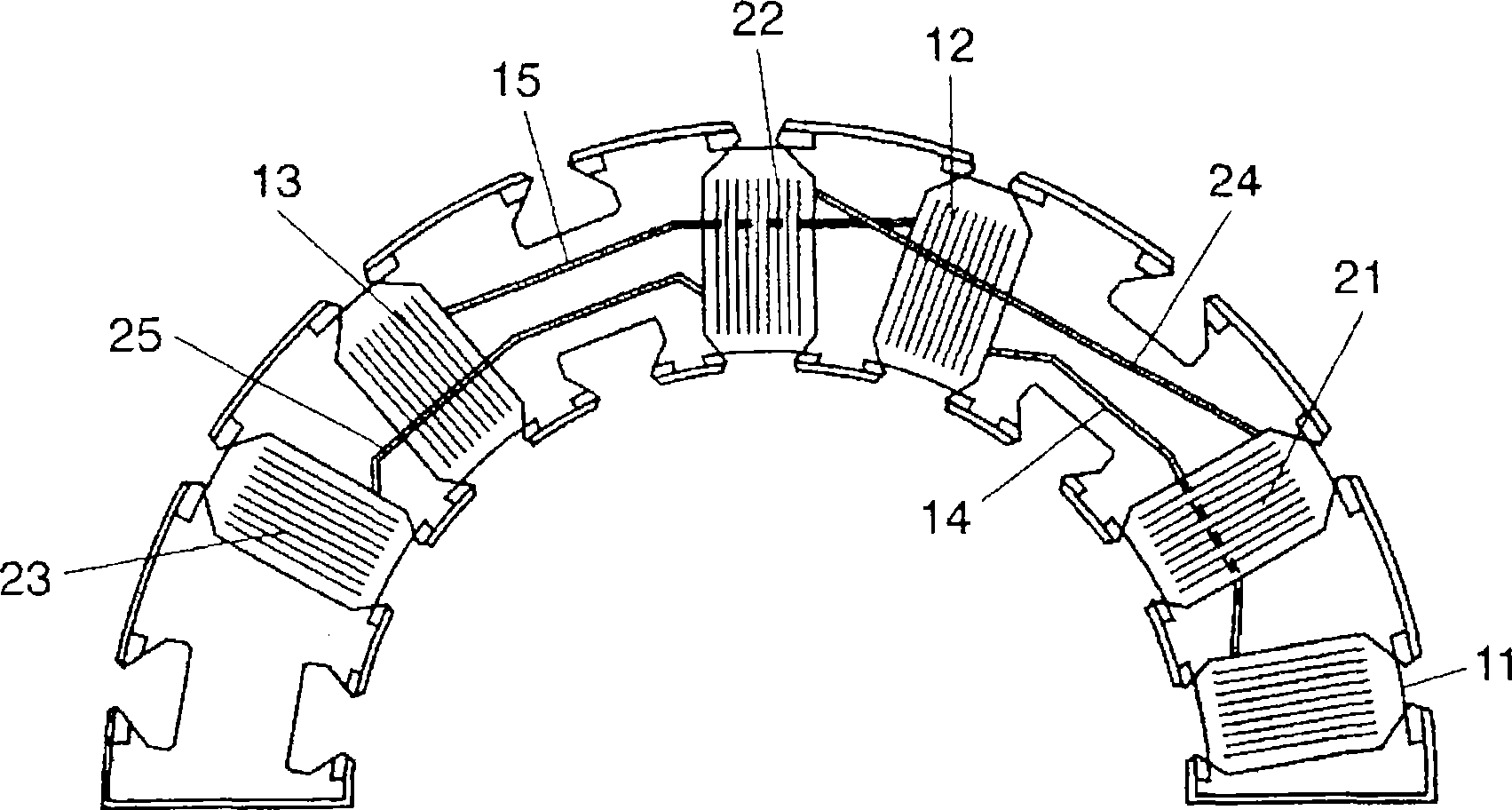
[0027] Next, if figure 2 As shown, coils 21 , 22 , 23 of the second phase are sequentially wound on stator core 1 via connection wires 24 , 25 . The connecting line 24 spans over the coil 12 of the first phase. Li...


PUM


Abstract

Each of a first phase, a second phase, and a third phase of a 3-phase winding has a plurality of troidal coils and crossover lines connecting the coils. The crossover line of the first phase passes inside the second-phase and the third-phase coil. The crossover line of the second phase is guided by a guide post and passes above the first-phase coil and passes inside the third-phase coil. The crossover line of the third phase is guided by a guide post and passes above the first-phase and the second-phase coil.

Description

technical field [0001] The present invention relates to a stator of a motor for home appliances and a molded motor using the stator. Background technique [0002] Recently, electric motors for home appliances are required to be highly efficient from the viewpoint of energy saving, and therefore, they are being converted to brushless motors. Along with this, a two-rotor three-phase brushless motor having magnet rotors inside and outside an annular stator has attracted attention (for example, refer to Patent Document 1 and Patent Document 2). [0003] When performing ring winding on a ring-shaped stator, usually, the ring-shaped stator core is divided into half. Next, if Figure 12 As shown, the first phase coil 60 is first wound leaving a space for the second phase coil, and then the second phase coil is wound in its space. At this time, the connecting wires connecting the coils come into contact with coils of different phases. Therefore, before winding the second phase co...

Claims


Application Information

Patent Timeline
IPC IPC(8): H02K3/28H02K3/04H02K3/34H02K3/44H02K15/095
CPCH02K3/52H02K3/46
Inventor 关育刚山崎昭彦中川幸典
Owner PANASONIC CORP
Why Eureka
Try Eureka