Ultrasonic diagnosis device, ultrasonic image analysis device, and ultrasonic image analysis method

A diagnostic device and image analysis technology, applied in echo tomography and other directions, can solve problems such as myocardial tissue distortion and inability to perform correct settings

Active Publication Date: 2009-06-24
TOSHIBA MEDICAL SYST CORP +1
View PDF1 Cites 7 Cited by
  • Summary
  • Abstract
  • Description
  • Claims
  • Application Information

AI Technical Summary

Problems solved by technology

[0009] In the case of selectively observing the parametric image data in the predetermined time period of the early diastole, it is difficult to accurately observe the myocardial tissue in the predetermined time period from the parametric image data continuously displayed as moving images conventionally. "skew" etc.

Method used


Image

  • Ultrasonic diagnosis device, ultrasonic image analysis device, and ultrasonic image analysis method
  • Ultrasonic diagnosis device, ultrasonic image analysis device, and ultrasonic image analysis method
  • Ultrasonic diagnosis device, ultrasonic image analysis device, and ultrasonic image analysis method

Examples


no. 1 approach

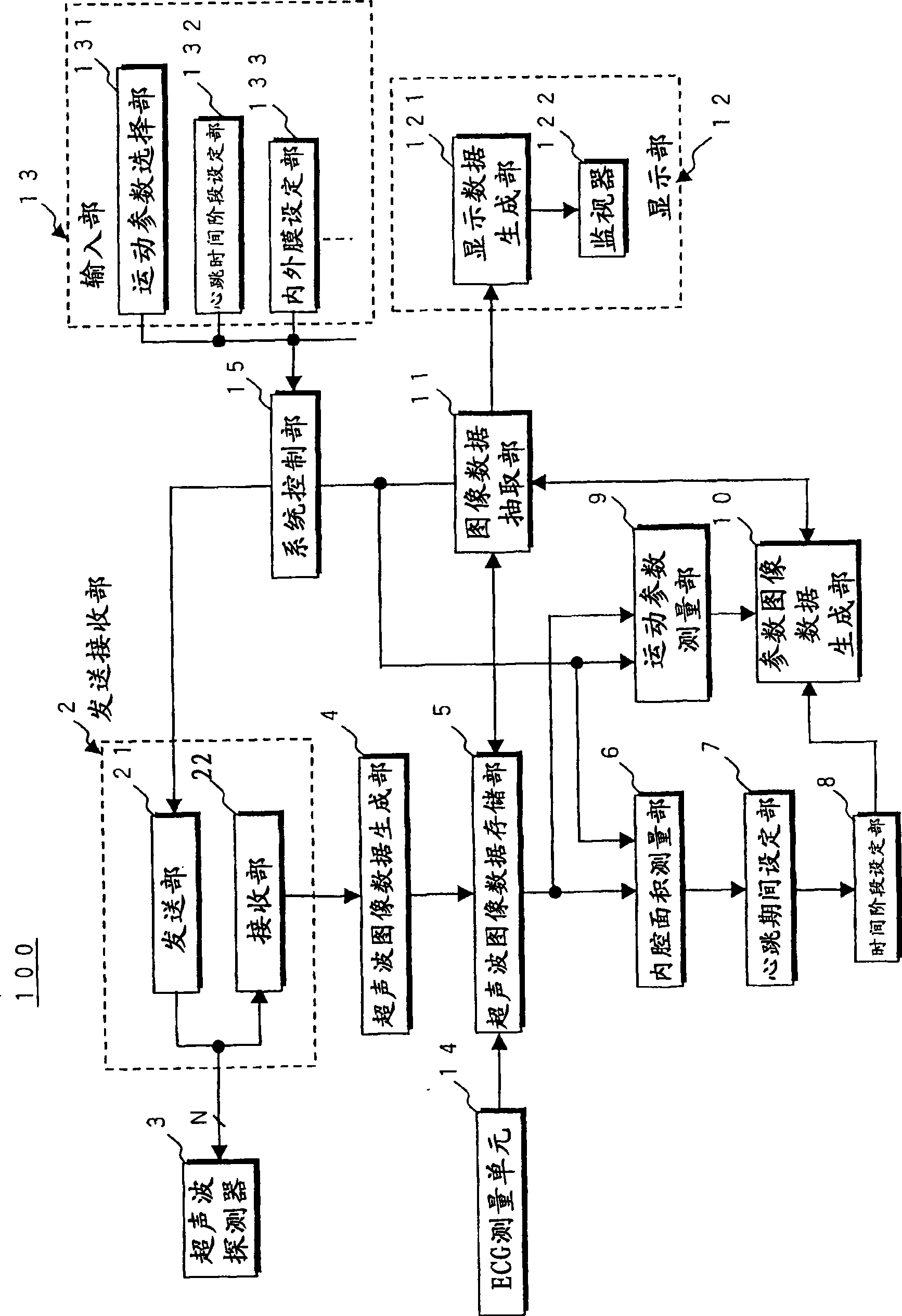
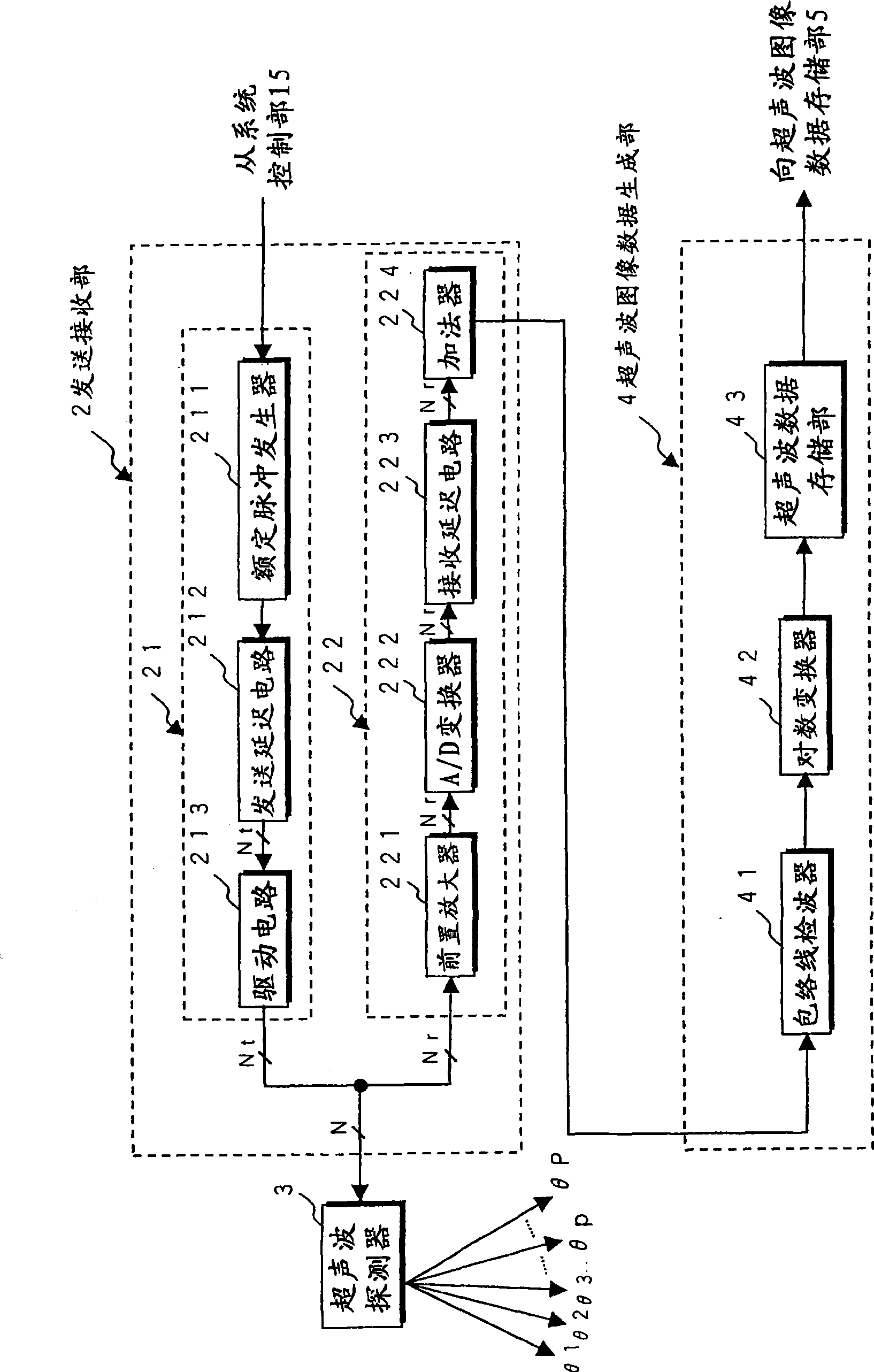
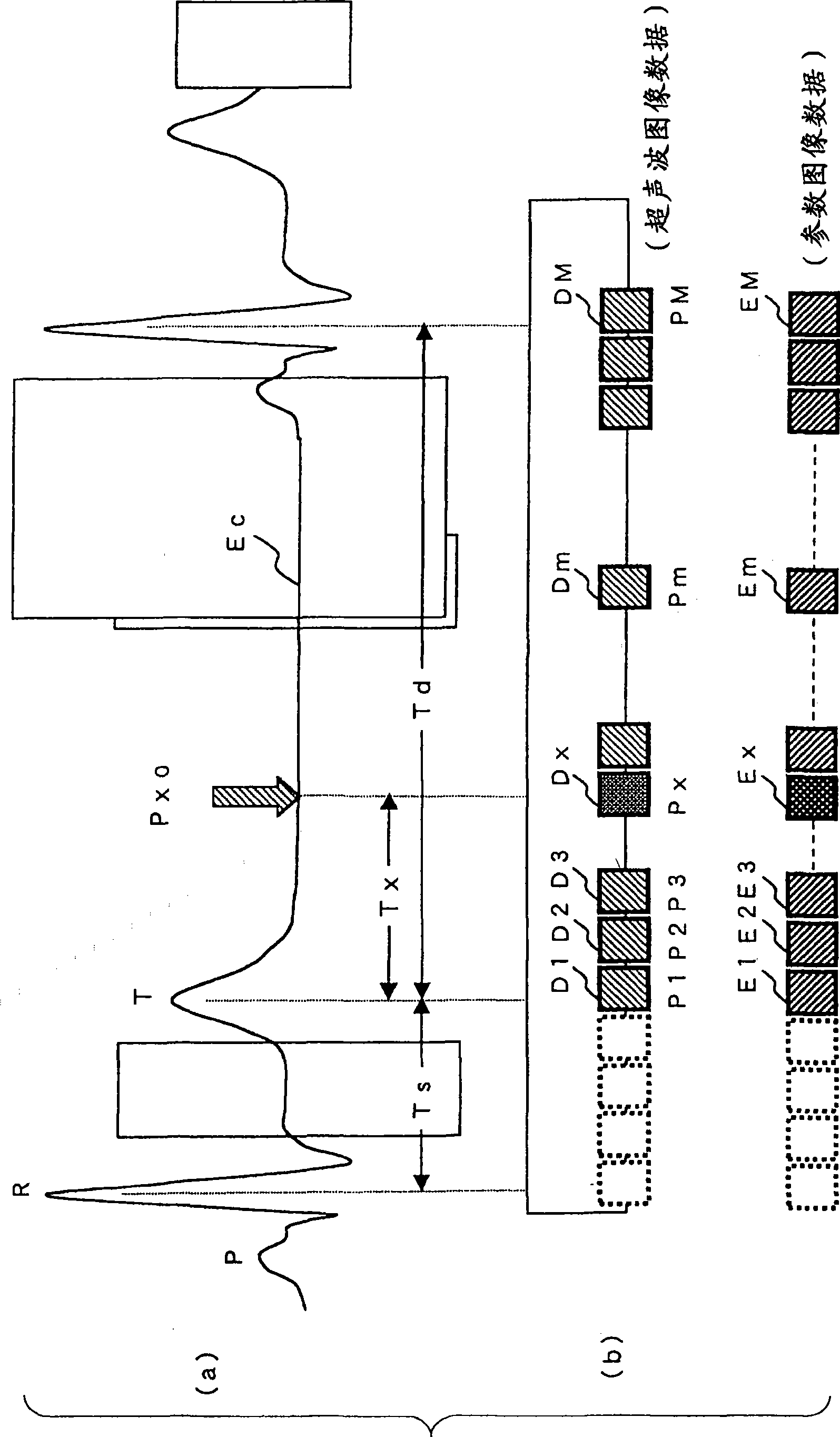
[0023] The ultrasonic diagnostic apparatus in the first embodiment of the present invention described below first transmits and receives ultrasonic waves to the subject to generate time-series B-mode image data as ultrasonic image data, and performs tracking processing on these ultrasonic image data to obtain The "skew (strain)" of myocardial tissue is measured two-dimensionally or three-dimensionally as a motion parameter. On the other hand, the end-systolic phase determined from the time period at which the area of ​​the cardiac chamber becomes the smallest using the ultrasonic image data, and the R wave in the electrocardiographic waveform of the subject measured in parallel with the collection of the ultrasonic image data For the determined end-diastole, set the diastolic heartbeat time phase based on the above-mentioned end-systolic phase, and add the diastolic heartbeat time phase to the time-series parameter image data generated based on the motion parameters of the ultr...

no. 2 approach

[0075] Next, a second embodiment of the present invention will be described. The ultrasonic image analysis device in the second embodiment first performs tracking processing on time-series ultrasonic image data collected in advance with R-wave timing information based on the electrocardiographic waveform of the subject, and two-dimensionally measures Motion parameters of myocardial tissue. On the other hand, the end-systolic phase specified based on the time period at which the area of ​​the cardiac chamber becomes the smallest using the ultrasonic image data and the end-diastolic phase specified using the R-wave timing information added to the ultrasonic image data are set based on the end-systolic phase. The time phase of the diastolic heartbeat is added to the time-series parameter image data generated based on the motion parameters of the ultrasonic image data. Then, the parametric image data of the diastolic heartbeat time phase closest to the desired diastolic heartbeat...


PUM


Abstract

The present invention provides an ultrasonic diagnosis device, an ultrasonic image analysis device and a method thereof. A motion parameter measuring unit (9) two-dimensionally measures a motion parameter of a myocardial tissue by a tracking process on time-series ultrasonic image data acquired by transmission and reception of ultrasonic waves to and from a sample. On the other hand, a time phase setting unit (8) adds a diastolic heartbeat time phase, which is set on the basis of a systole end specified by a time phase where a cardiac cavity area of the ultrasonic image data is the smallest and a diastole end specified by an R wave in an electrocardiographic waveform of the sample, relative to the systole end to time-series parameter image data generated by a parameter image data generating unit (10) on the basis of the motion parameter. An image data extracting unit (11) extracts parameter image data to which the diastolic heartbeat time phase closest to a desired diastolic heartbeat time phase set by an input unit (13) is added and displays the extracted parameter image data on a display unit (12).

Description

technical field [0001] The present invention relates to an ultrasonic diagnostic apparatus, an ultrasonic image analysis apparatus, and an ultrasonic image analysis method, and particularly to an ultrasonic diagnostic apparatus capable of generating and displaying parametric image data based on motion parameters such as cardiac muscle by analyzing ultrasonic image data collected from a subject, An ultrasonic image analysis device and an ultrasonic image analysis method. Background technique [0002] Ultrasonic diagnostic equipment emits ultrasonic pulses generated from the vibrating element built in the ultrasonic probe into the subject, and uses the vibrating element to receive ultrasonic reflected waves generated due to differences in the acoustic impedance of the subject's tissues and display them on the monitor. superior. This diagnostic method can easily observe real-time two-dimensional image data by simply touching the ultrasonic probe to the body surface, so it is w...

Claims


Application Information

Patent Timeline
IPC IPC(8): A61B8/13
Inventor 川岸哲也阿部康彦大内启之石井克尚
Owner TOSHIBA MEDICAL SYST CORP
Why Eureka
Try Eureka