Non-circular gear transmission and its transmission mechanism

A non-circular gear, transmission mechanism technology, applied in the direction of gear transmission, transmission, belt/chain/gear, etc., can solve the problems of high energy consumption, large negative torque, large peak value, etc.

Inactive Publication Date: 2009-06-24
BEIJING FENGYUAN TECH
View PDF0 Cites 17 Cited by
  • Summary
  • Abstract
  • Description
  • Claims
  • Application Information

AI Technical Summary

Problems solved by technology

Therefore, the net torque 3 of the traditional beam pumping unit has a large peak value and a deep valley value (negative value), and the fluctuation is relatively large, which brings a series of disadvantages:
[0010] 1. Large torque, in order to ensure the traditional beam pumping unit ( figure 1 ) normal operation requires the configuration of a high-power motor, which consumes electric energy;
[0011] 2. Motor 2 is in a low power factor state for a long time, which will deteriorate the power supply quality of the grid;
[0012] 3. The output shaft 17 of the reducer is the equivalent torque on the crankshaft (the root mean square torque is large) and the energy consumption is large;
[0013] 4. The negative torque is large, so that the traditional beam pumping unit ( figure 1 ) work in frequent positive and negative working conditions, the impact load is large, the transmission performance is poor, and at the same time, the motor feeds back and sends power to the grid
The current cylindrical gear reducer obviously cannot meet this demand.

Method used


Image

  • Non-circular gear transmission and its transmission mechanism
  • Non-circular gear transmission and its transmission mechanism
  • Non-circular gear transmission and its transmission mechanism

Examples


Embodiment Construction

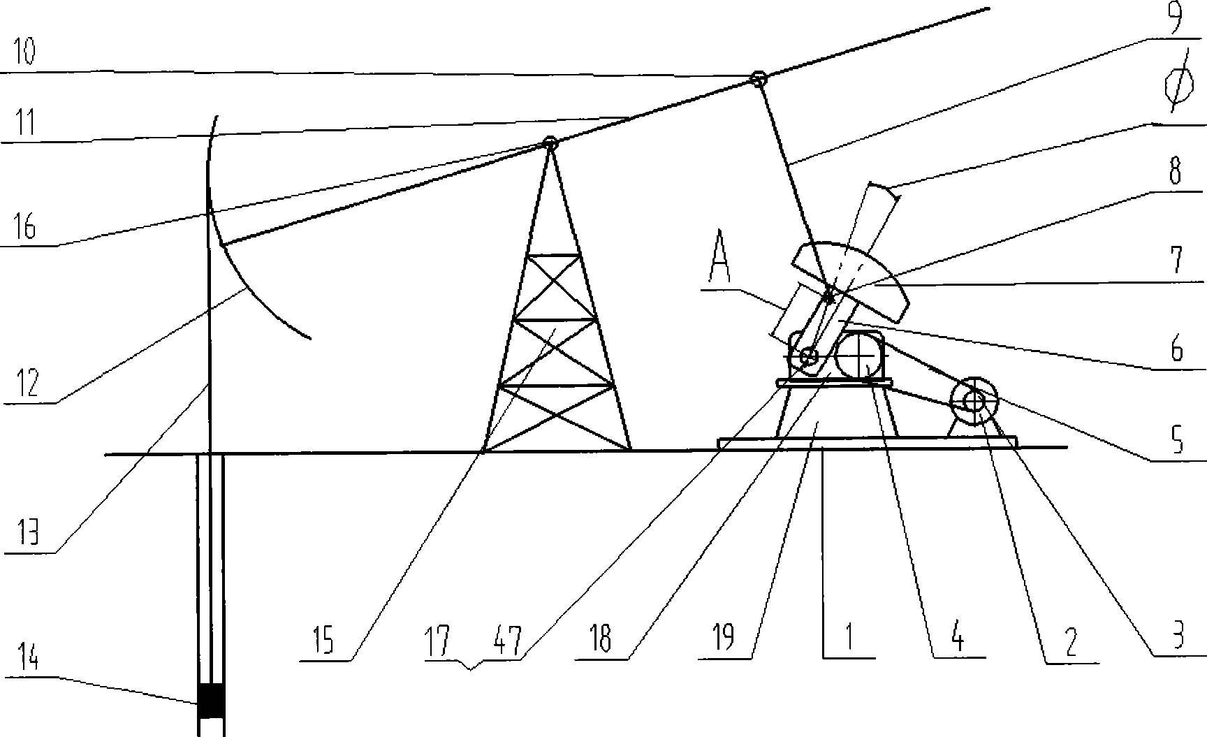
[0070] Non-circular gear gearbox and transmission mechanism thereof described in the present invention ( Figure 4 ), which can provide an output torque that is dynamically adapted and balanced with the host load variation.

[0071] As an example, we installed it on a traditional beam pumping unit, achieving the goals of convenience, stability, and greatly improving the energy-saving effect of the traditional beam pumping unit. Below we describe the embodiment of the present invention respectively.

[0072] 1. The specific implementation of the non-circular gear box.

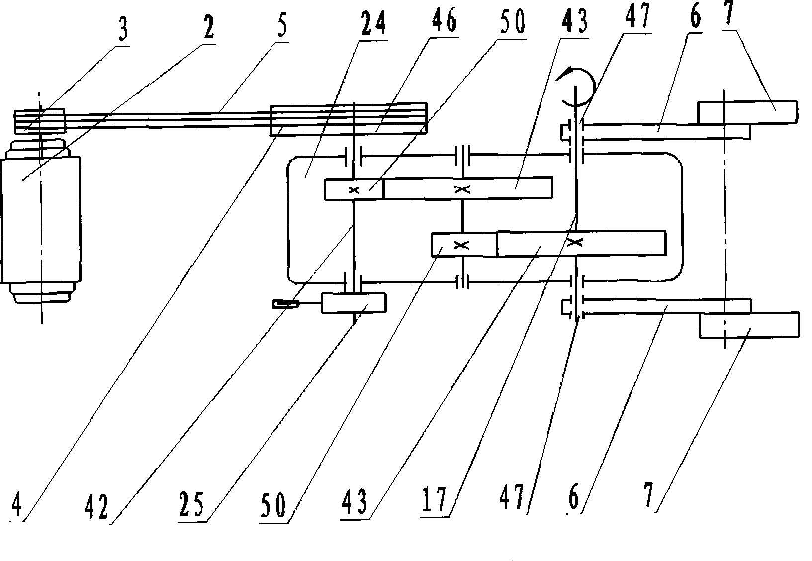
[0073] Figure 5 , Figure 6 , Figure 7 , Figure 8 Shown that the non-circular gear gearbox 24 is composed of a casing 26, a first non-circular gear 27, a second non-circular gear 28, an oil window 29, an output shaft end cover 30, a bolt assembly 31, a ventilation cover 32, an observation window 33, Case cover 34, output shaft bearing 35, large sprocket flat key 36, input shaft bearing 37, non-circular ...


PUM


Abstract

The invention relates to a non-circular gear transmission case and a transmission mechanism thereof. The transmission mechanism is a combined type transmission mechanism with a non-uniform velocity ratio, comprising a non-circular gear transmission case (24), a low speed motor (20), a chain wheel train (21, 22, 23) or a belt wheel train. The output torque and the output rotating speed of the transmission mechanism are consistent with a mainframe load change form; therefore, the transmission mechanism can save energy by a big margin when being used in a mechanism requiring transmission with a non-uniform velocity ratio. The pitch curve shape of non-circular gears (27, 28), and geometric and initial position parameters are determined by an optimized design according to the mainframe load change form, continuity of the pitch curve and fabrication procedure and the like. When the non-circular gears (27, 28) are connected with a circular gear train and a circular gear planetary gear train power, non-circular gear transmission cases of various forms can be formed. An energy-saving beam pumping unit can be formed by removing a speed reducer, a belt wheel and an electric motor and installing the non-circular gear transmission case and the transmission mechanism thereof on a conventional beam pumping unit.

Description

technical field [0001] The invention relates to a non-circular gear box with non-uniform speed ratio transmission and its transmission mechanism, and relates to equipment requiring non-uniform speed ratio transmission in the machinery industry and beam pumping units in petroleum mechanical oil production equipment. It belongs to the field of mechanical equipment. Background technique [0002] The background technology will be described by taking the traditional beam pumping unit in petroleum mechanical oil extraction equipment as an example. [0003] At present, my country and the oil-producing countries in the world adopt oil, and all adopt pumping units to extract oil in oil wells. The most widely used is the beam pumping unit, and its working principle is as follows: [0004] figure 1 It shows a traditional beam pumping unit which consists of a base plate 1, a motor 2, a small pulley 3, a large pulley 4, a belt 5, a crank 6, a balance weight 7, a connecting rod hub 8, ...

Claims


Application Information

Patent Timeline
Patent Type & Authority Applications(China)
IPC IPC(8): F16H35/02F16H1/28F16H7/02F16H7/06E21B43/00H02K7/10
Inventor 吴序堂贺敬良董剑荣世德张瑞陶青潘峰
Owner BEIJING FENGYUAN TECH
Why Eureka
Try Eureka