Division board used for debugging large-multiplying power continuous zooming camera system

A camera system and high magnification technology, applied in the field of optical instruments, can solve problems such as thick engraved lines, inability to align with the reference electric "cross" line, and affect debugging accuracy, so as to achieve accurate debugging effect

Inactive Publication Date: 2009-06-24
CHANGCHUN INST OF OPTICS FINE MECHANICS & PHYSICS CHINESE ACAD OF SCI
View PDF0 Cites 3 Cited by
  • Summary
  • Abstract
  • Description
  • Claims
  • Application Information

AI Technical Summary

Problems solved by technology

Can't see clearly or almost no reticle crosshairs, which will affect the debugging accuracy
Or order a wide reticle, the reticle crosshair can be seen on the monitor when the zoom camera system is short focal length imaging, but the reticle crosshair should be magnified more than ten times when the telephoto imaging is performed, such as Figure 4 , the engraved line is quite thick, and cannot be aligned with the reference electric "cross" line 7, which affects the debugging accuracy

Method used


Image

  • Division board used for debugging large-multiplying power continuous zooming camera system
  • Division board used for debugging large-multiplying power continuous zooming camera system
  • Division board used for debugging large-multiplying power continuous zooming camera system

Examples


Embodiment Construction

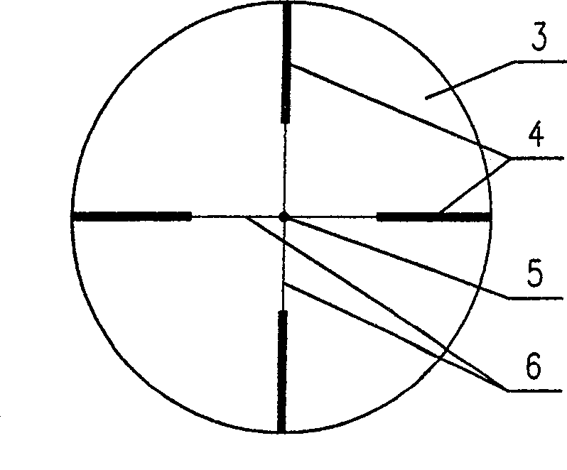
[0016] The invention according to figure 2 The graphic structure shown is implemented, and the manufacturing method is the same as that of a common reticle, that is, black graphics are engraved on the glass substrate 3, and the common methods for making a reticle can be adopted: plate-making photography, wax engraving and acid etching, etc. The width of the fine engraved line 6 is generally 0.1 mm, the width of the thick engraved line 4 is ten times the width of the fine engraved line 6, which is 1 mm, the diameter of the central point 5 is the same as the width of the thick engraved line 4, and the depth of the engraved line is the same as that of ordinary The reticle is the same, and there is no requirement here. The glass substrate 3 is made of K9 glass, and its size can be made according to needs.


PUM


Abstract

The invention relates to a reticle plate for debugging a large-magnification continuous camera system, and belongs to the technical field of optical instruments. The invention aims to solve the technical problem that the invention provides the reticle plate for debugging the large-magnification continuous camera system. The invention aims to solve the technical scheme that the reticle plate comprises a glass substrate, two thick reticles, a central point and two thin reticles; the two mutually vertical thin reticles are inscribed on the glass substrate, the intersecting point thereof is positioned at the symmetrical center of the glass substrate, and the length thereof is the radius of the glass substrate; the central point is inscribed at the symmetrical center, the center thereof is superposed with the symmetrical center; the two mutually vertical thick reticles which are disconnected from the middle part are inscribed on the glass substrate, and the symmetrical center thereof is positioned on the symmetrical center of the glass substrate; the two thin reticles are adjacent to the symmetrical center; the two thick reticles which are disconnected with the middle part are adjacent to the edge; the thin reticles are connected with the two thick reticles; and the length of each thick reticle is half of the radius of the glass substrate, namely the glass substrate is divided into four equal parts by the two mutually vertical thin reticles and the two mutually vertical thick reticles.

Description

Technical field: [0001] The invention belongs to the technical field of optical instruments and relates to a reticle used for debugging a large-magnification continuous zoom camera system. Background technique: [0002] The so-called large-magnification continuous zoom camera system means that the change magnification (zoom) of the long and short focal lengths of the camera system exceeds ten times or more. [0003] The debugging of the optical system is mostly carried out through the collimator. The collimator can be used as an infinite target to provide parallel light beams. It is composed of a light source, a reticle and an optical system. The pattern of the reticle placed in the focal plane of the collimator objective plays a crucial role. [0004] The closest prior art with the present invention is the crosshair (mutually perpendicular crosshairs) reticle that is usually equipped with by the manufacturer when purchasing a collimator, such as figure 1 As shown, a blac...

Claims


Application Information

Patent Timeline
Patent Type & Authority Applications(China)
IPC IPC(8): G02B27/32
Inventor 刘家燕
Owner CHANGCHUN INST OF OPTICS FINE MECHANICS & PHYSICS CHINESE ACAD OF SCI
Why Eureka
Try Eureka