Non-contact infrared control device

A control device, non-contact technology, applied in non-electrical signal transmission systems, remote control tuning using electromagnetic waves, signal transmission systems, etc., can solve the problems of insufficient affinity of the adjustment unit, not beautiful enough, and the panel is cumbersome, etc., to achieve convenient operation, application, enhancement Affinity, simple and beautiful panel effect

Inactive Publication Date: 2009-06-24
戚建春 +3
View PDF0 Cites 9 Cited by
  • Summary
  • Abstract
  • Description
  • Claims
  • Application Information

AI Technical Summary

Problems solved by technology

Most of the existing adjustment devices use potentiometer knobs, digital knobs, buttons, remote control, etc., which are more convenient to control, but in terms of

Method used


Image

  • Non-contact infrared control device
  • Non-contact infrared control device
  • Non-contact infrared control device

Examples


Embodiment Construction

[0043] The present invention will be further described below in conjunction with the accompanying drawings and embodiments.

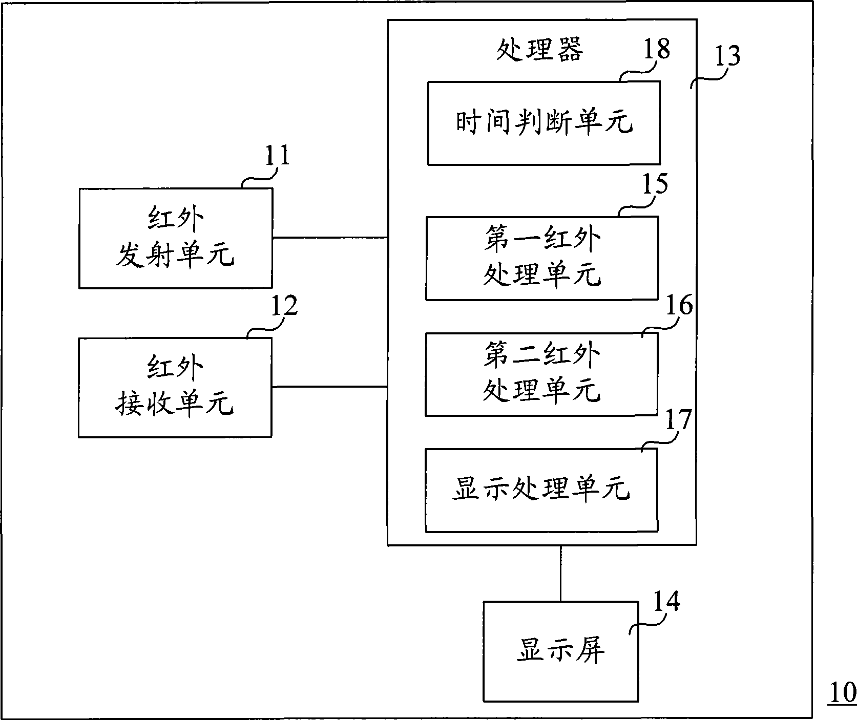
[0044] figure 1 The first embodiment of the non-contact infrared control device of the present invention is shown. like figure 1 As shown, the device 10 includes an infrared emitting unit 11, an infrared receiving unit 12, a processor 13 and a display screen 14, wherein the processor 13 includes a time judging unit 18, a first infrared processing unit 15, a second infrared processing unit 16 and a display processing unit 17.

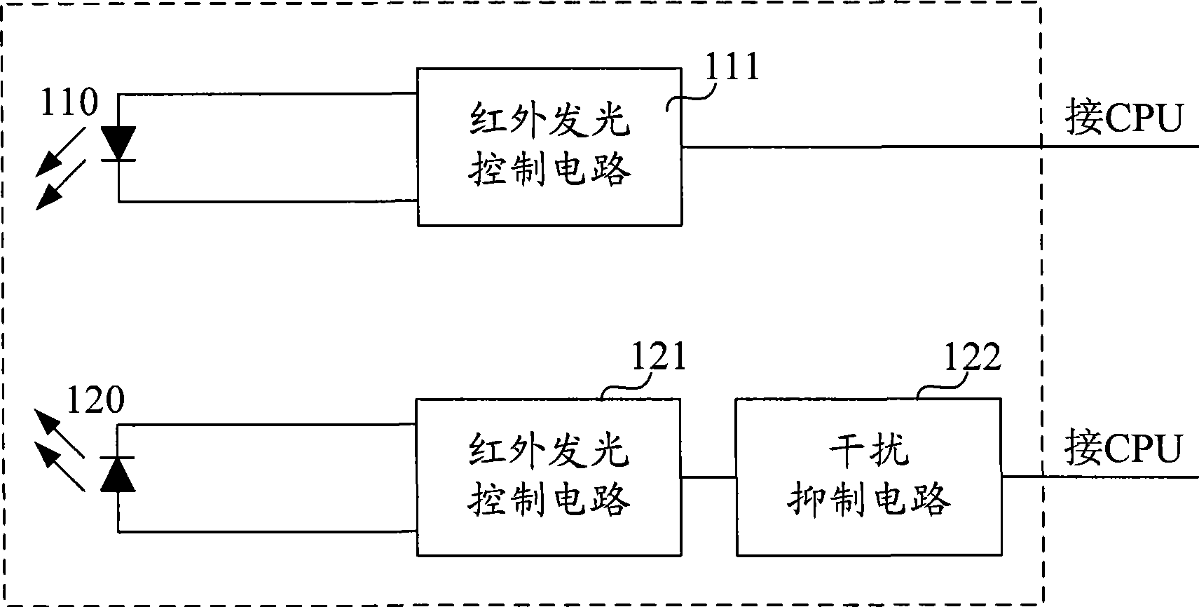
[0045] See also figure 2 , the infrared emitting unit 11 is composed of an infrared light emitting tube 110 and an infrared light emitting control circuit 111 , and the infrared light emitting control circuit 111 is connected to the processor 13 . The processor 13 controls the infrared light emitting tube 110 to emit an infrared signal through the infrared light emitting control circuit 111 . The infrared receiving unit 12 i...


PUM


Abstract

The invention discloses a non-contact infrared control device. The non-contact infrared control device is installed in a device required for controlling and adjusting a plurality of parameters in an embedded manner, so that the control and the adjustment are more convenient and rapid, and the interaction is more natural. The non-contact infrared control device adopts the technical scheme that an infrared receiving unit is utilized to receive an infrared ray signal sent by an infrared emitting unit then reflected, and then an infrared processing unit is utilized to judge the received infrared ray signal (such as, the existence or not, the increase or decrease, the specified order of the signal, and the like) so as to output various control signals. The invention is applied to the field of infrared control.

Description

technical field [0001] The invention relates to a control device, in particular to a non-contact control device using infrared signals. Background technique [0002] Many electrical equipment, especially audio-visual equipment, are equipped with adjustment units, such as the adjustment of volume and color. Taking the radio as an example, the adjustment unit on the radio needs to control the volume, perform frequency search, etc. Most of the existing adjustment devices use potentiometer knobs, digital knobs, buttons, remote control, etc., which are more convenient to control, but in terms of interactivity, the affinity of these adjustment units is not enough. Too many adjustment knobs on the panel also make the panel too cumbersome and not beautiful enough. Contents of the invention [0003] The purpose of the present invention is to solve the above problems. It provides a non-contact infrared control device, which can be embedded and installed in equipment that needs to ...

Claims


Application Information

Patent Timeline
IPC IPC(8): G08C23/04H03J9/06
Inventor 戚建春林展鸿马伟刚张俊杰
Owner 戚建春
Why Eureka
Try Eureka