
Porous printing press

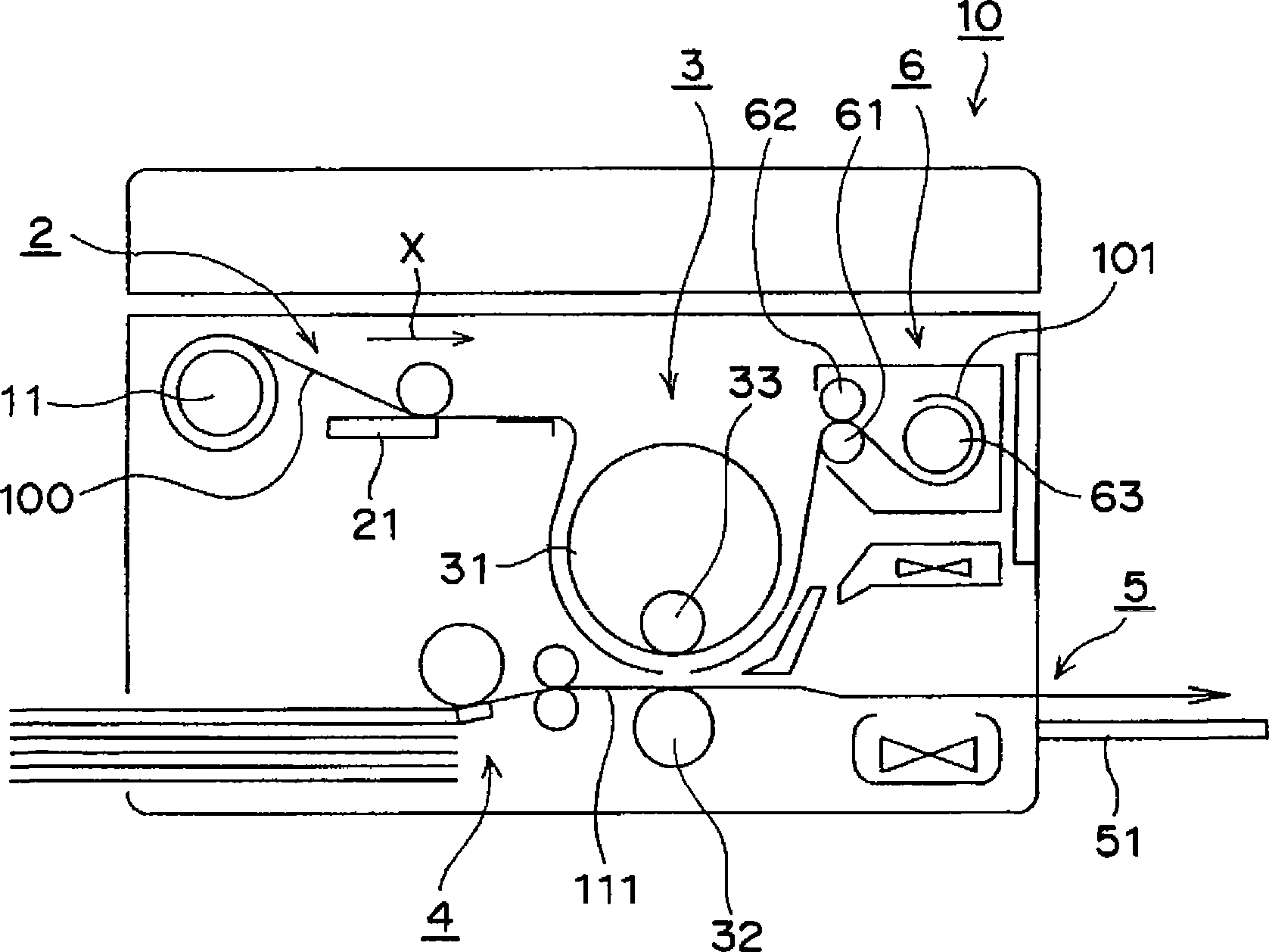
A technology for printing presses and stencils, used in printing, stencil printing equipment, office printing equipment, etc., to solve problems such as accidental disengagement from the core and dirtying the operator.

Inactive Publication Date: 2009-06-24
DUPLO SEIKO CORP
View PDF2 Cites 0 Cited by
  • Summary
  • Abstract
  • Description
  • Claims
  • Application Information

AI Technical Summary

Problems solved by technology

Therefore, when the core is taken out and the wound discharged stencil base paper is discarded, the discharged stencil base paper may be accidentally detached from the core and soil the operator's clothes, etc.

Method used


Image

  • Porous printing press
  • Porous printing press
  • Porous printing press

Examples


Embodiment

[0052] As Examples 1 and 2 and Comparative Example 1, winding conditions were set as shown in Table 1, and predetermined winding tests were performed to evaluate winding performance.

[0053] (winding condition)

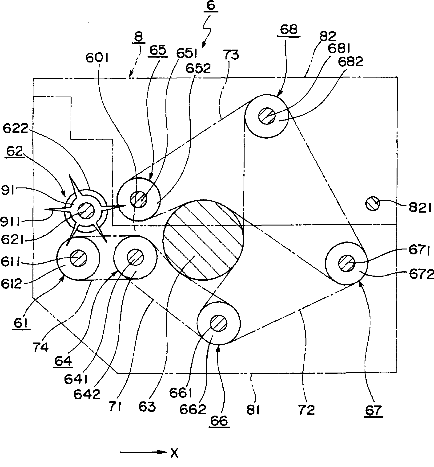
[0054] The rotational speed and rotational linear speed A of the first winding roller 64 , the rotational speed and rotational linear speed B and A / B of the lead-in roller 61 were set as shown in Table 1. The outer diameters of the first winding roller 64 and the introduction roller 61 are both 22 mm.

[0055] [Table 1]

[0056] [Table 1]

[0057]

[0058] (winding test)

[0059] A stencil base paper is considered used after five sheets have been printed. The used stencil paper (ie, the discharged stencil paper) is discharged and wound on the core 63 .

[0060] (Evaluation of Winding Performance)

[0061] Every ten sheets of discharged stencil paper were wound, the outer diameter D of the core including the wound discharged stencil paper was measured, and th...


PUM


Abstract

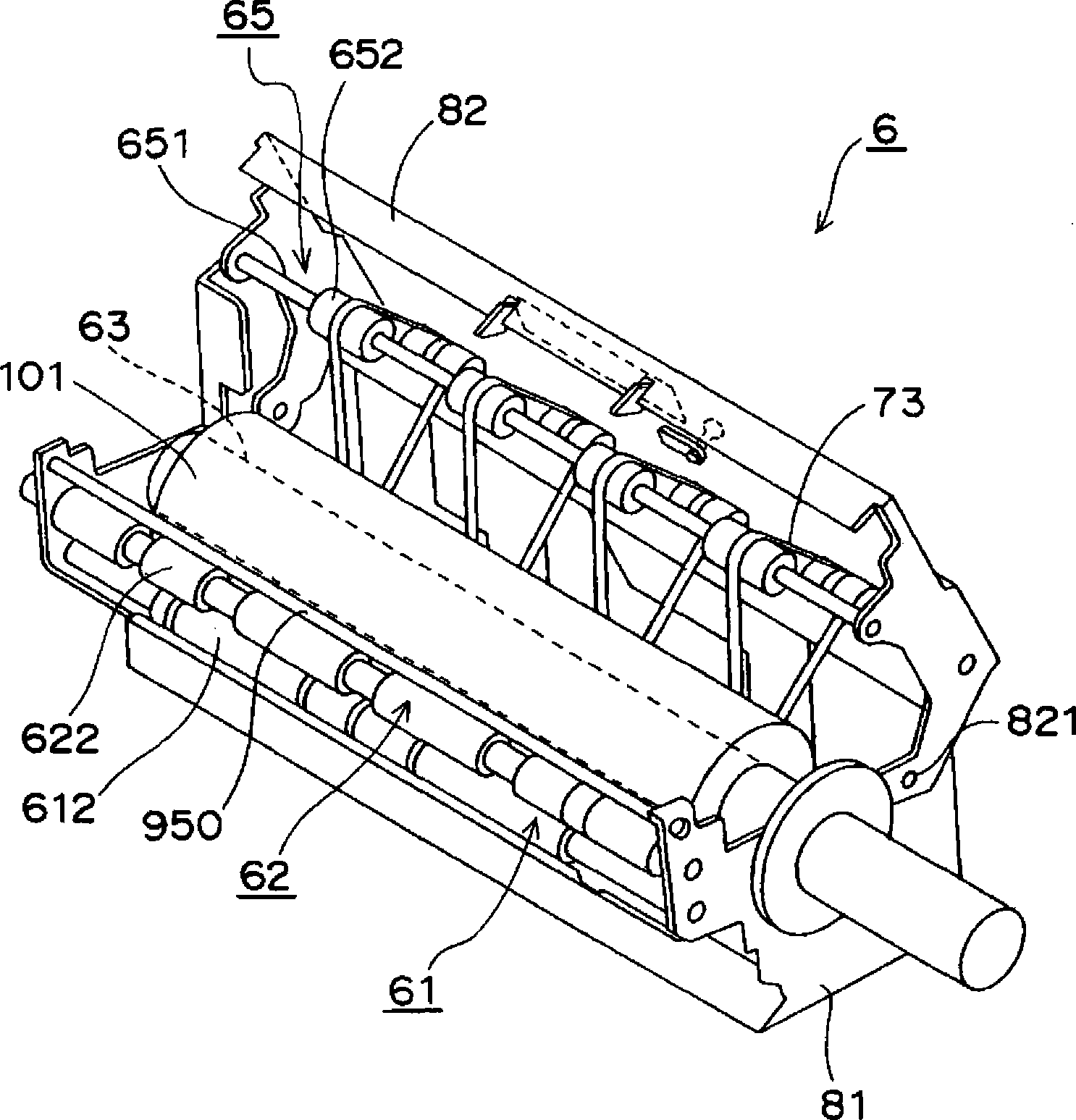
Provided is a mimeograph printer comprising a plate discharging device (6). This plate discharging device includes a pair of vertical pulling rollers (61, 62) for pulling and clamping a discharged stencil paper (101) from a plate mounting member (31) and for conveying the same, while rotating, to a next stage, a winding core (63) for winding up the discharged stencil paper (101) conveyed by the pulling rollers, a plurality of take-up rollers (64, 65, 66) arranged to enclose the winding core, and first to third supporting belt members (71, 72, 73) adapted to run between the take-up rollers in a manner to support the winding core (63) therearound, and to rotate together, as the take-up rollers rotate, thereby to rotate the winding core. The mimeograph printer is characterized in that the first take-up roller (64) has its linear velocity set to 1.38 times as high as that of the pulling roller (61) or higher.

Description

technical field [0001] The present invention relates to a stencil printing machine provided with a plate discharge device that removes used stencil base paper (hereinafter referred to as "discharged stencil base paper") from a stencil mount and recovers it while winding it. Background technique [0002] As a plate discharge device of a stencil printing machine, there are known a plate discharge device that collects the discharged stencil base paper while winding it on a core (see Patent Document 1) and a plate discharge device that compresses and stores the discharged stencil base paper and collects it. (Refer to Patent Document 2). [0003] In the device of Patent Document 1, as the discharged stencil paper is wound on the core, the radius from the center of the core to the outermost discharged stencil paper gradually increases, and the discharged stencil paper is wound on the core. up until the radius reaches the specified size. Once the above-mentioned radius reaches th...

Claims


Application Information

Patent Timeline
IPC IPC(8): B41L13/14
CPCB41L13/14
Inventor 佐藤太一
Owner DUPLO SEIKO CORP
Learn More