pneumatic tire

A technology of pneumatic tires and tires, which is applied to tire parts, tire edges, tire sidewalls, etc., can solve problems such as insufficient research, achieve excellent durability, and promote heat dissipation

Active Publication Date: 2019-05-07
SUMITOMO RUBBER IND LTD
View PDF6 Cites 0 Cited by
  • Summary
  • Abstract
  • Description
  • Claims
  • Application Information

AI Technical Summary

Problems solved by technology

Various studies have been conducted on the arrangement and shape of the dimples 4, but studies on the reinforcement effect of the land portion 6 are insufficient.

Method used


Image

  • pneumatic tire
  • pneumatic tire
  • pneumatic tire

Examples


Embodiment 1

[0078] Prototype Figure 1 ~ Figure 3 tires shown. The size of this tire is 245 / 75R16. The specifications of the concavo-convex portion in this Example 1 are shown in Table 1 below.

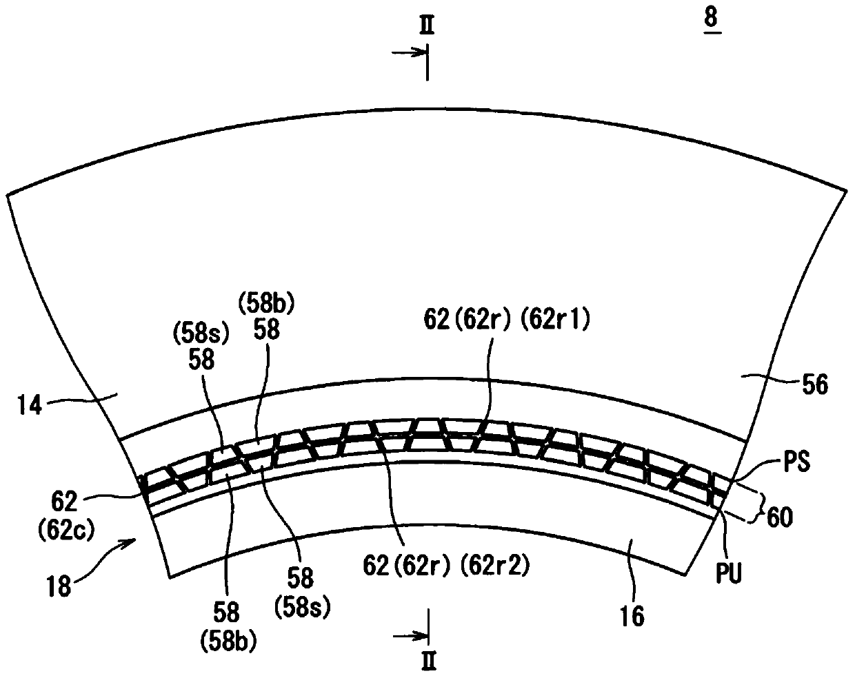
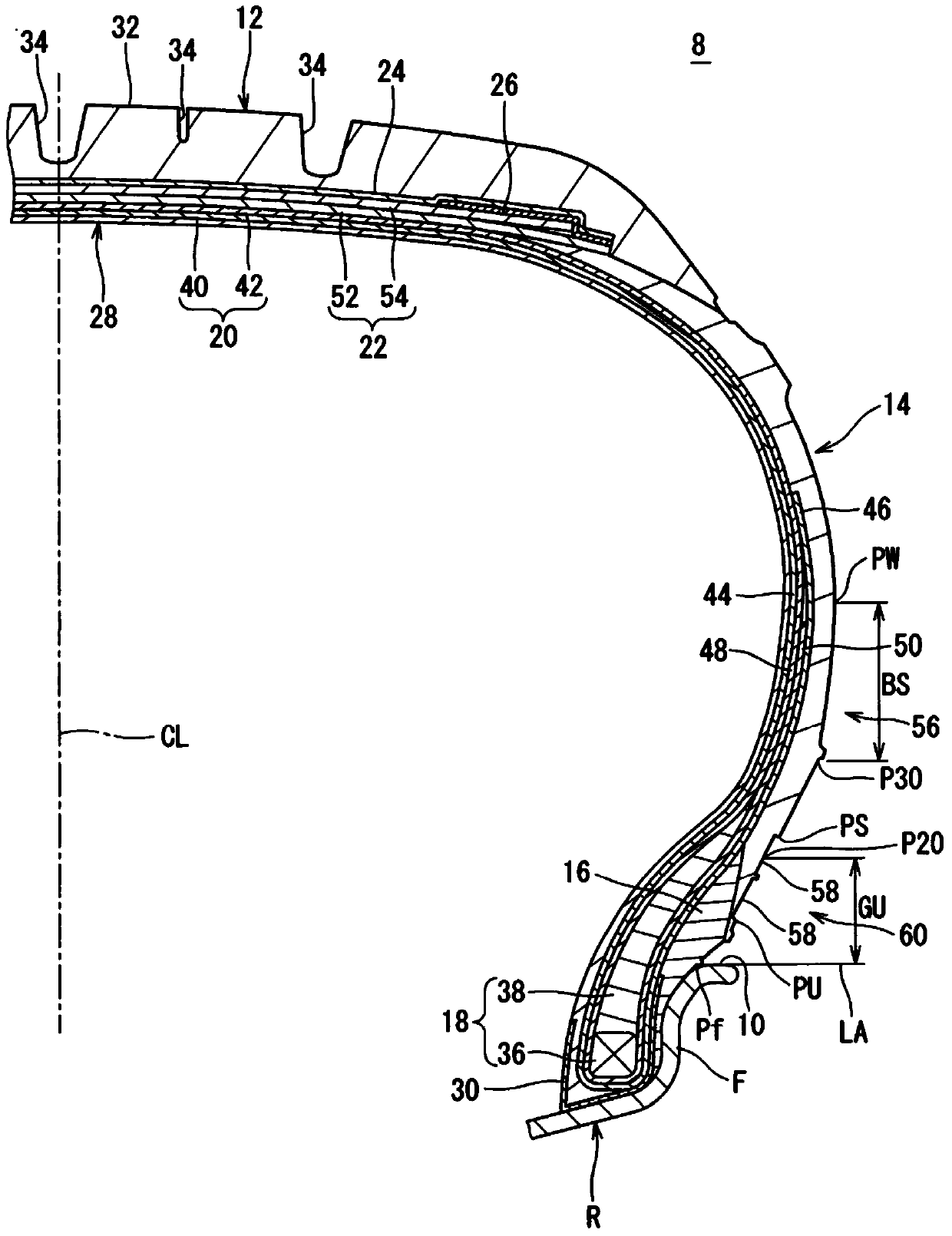
[0079] In this tire, the outer edge PS of the concavo-convex portion is located radially inward from the position P30. This case is indicated by "GS" in the column of "outer edge of concavo-convex part" in Table 1. The inner edge PU of the concavo-convex portion is located between the position Pf and the position P20 in the radial direction. This case is represented by "GU" in the column of "inner edge of concavo-convex part" in Table 1.

[0080] No filler is provided in this tire. This is indicated by "N" in the "Filler" column of Table 1. The carcass of the tire is as figure 2 As shown, it consists of two carcass plies.

Embodiment 2 and comparative example 3

[0084] Tires of Example 2 and Comparative Example 3 were obtained in the same manner as in Example 1, except that the inner edge PU of the concavo-convex portion was arranged radially outward from the position P20. The inner edge PU of the concave-convex portion is located radially outward from the position P20, which is indicated by “BU” in the column “Inner edge of the concave-convex portion” in Table 1. In Comparative Example 3, the outer edge PS of the concavo-convex portion is located between the position PW and the position P30 in the radial direction. This case is indicated by "BS" in the column of "outer edge of concavo-convex part" in Table 1.

Embodiment 3 and comparative example 4~6

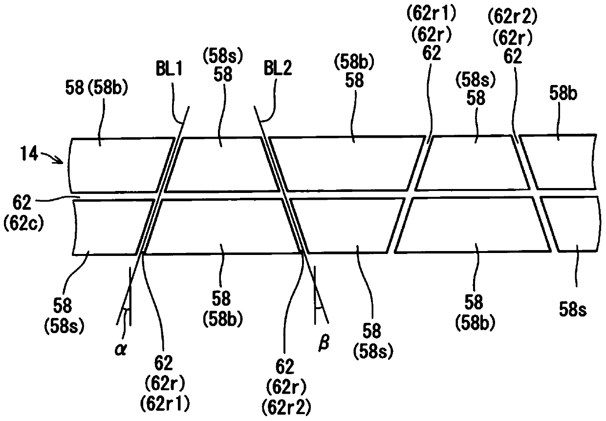
[0086] Tires of Example 3 and Comparative Examples 4 to 6 were obtained in the same manner as in Example 1 except that the structure of the concavo-convex portion was shown in Table 2 below. In Example 3, a triangular dimple is formed between the first land portion and the second land portion.


PUM


Abstract

A pneumatic tire 8 has a roughened region 60 on its side surface 56. The roughened region 60 includes numerous lands 62, and a dimple 58 is present between two lands 62. The lands 62 include first lands (62r1) and second lands (62r2). First lands (62r1) and second lands (62r2) are alternately arranged in a circumferential direction. The first lands (62r1) and second lands (62r2) are set to incline relative to a radial direction. The inclination direction of first lands (62r1) is opposite the inclination direction of second lands (62r2). When the tire 8 is mounted on a normal rim and is filled with air at a normal inflation pressure, the outer periphery of the roughened region 60 is located on the radially inner side of a position 30 mm away in a radially inward direction from the tire maximum-width position. The inner periphery of the roughened region 60 is located on the radially outer side of the radially outer edge of the rim.

Description

technical field [0001] The present invention relates to pneumatic tires. More specifically, the present invention relates to pneumatic tires for small trucks. Background technique [0002] The tires support the body. Apply load to the tire. As a result the tire deflects. Deflection causes deformation. Deformation tends to concentrate on the boundary between the carcass and the apex, the front end of the apex, and the boundary between the carcass and the edge. If the deformation is concentrated, damage such as slack and loose cords may occur. [0003] Deformation is deformation and will be accompanied by heat. Therefore, there is a possibility that not only mechanical deterioration but also thermal deterioration may develop in the deformed portion. [0004] In some cases, a concavo-convex portion in which a plurality of dimples is arranged is provided on the side surface of the tire. Figure 4 ~ Figure 6 Shown is an arrangement example of the dimples 4 in the concavo-c...

Claims


Application Information

Patent Timeline
Patent Type & Authority Patents(China)
IPC IPC(8): B60C13/00B60C15/00
CPCB60C13/02
Inventor 柳生健太郎汤川直树御手洗康男国安恭彰
Owner SUMITOMO RUBBER IND LTD
Why Eureka
Try Eureka