Speed look-ahead control method based on filter technique

A speed forward-looking and filtering technology, which is applied in the direction of program control, computer control, general control system, etc., can solve the problems of unsmooth speed curve, inability to calculate connection speed, inability to meet high-speed processing and high sampling frequency, etc.

Active Publication Date: 2009-07-01
SHENYANG GOLDING NC & INTELLIGENCE TECH CO LTD
View PDF0 Cites 36 Cited by
  • Summary
  • Abstract
  • Description
  • Claims
  • Application Information

AI Technical Summary

Problems solved by technology

Although the continuous processing of the trajectory is theoretically realized, there are still the following problems: if the forward-looking processing adopts a linear acceleration and deceleration strategy, there will inevitably be sudden acceleration and deceleration during the interpolation process, and the speed curve is not smooth, which is not suitable for high-speed machining; if the forward-looking processing The S-curve acceleration and deceleration strategy is adopted. Since the S-curve acceleration and deceleration method is inherently using polynomials to divide the speed planning into 5 or 7 segments, the amount of calculation is huge and the programming is complicated.
If this method is used to iteratively calculate the transition speed, it will inevitably fail to meet the high-sampling frequency requirements of high-speed machining; when the actual running time of the path segment does not meet the integer multiple of the interpolation cycle, the transition speed cannot be calculated according to the speed transition mathematical model

Method used


Image

  • Speed look-ahead control method based on filter technique
  • Speed look-ahead control method based on filter technique
  • Speed look-ahead control method based on filter technique

Examples


Embodiment Construction

[0053] The present invention will be further described below in conjunction with accompanying drawing.

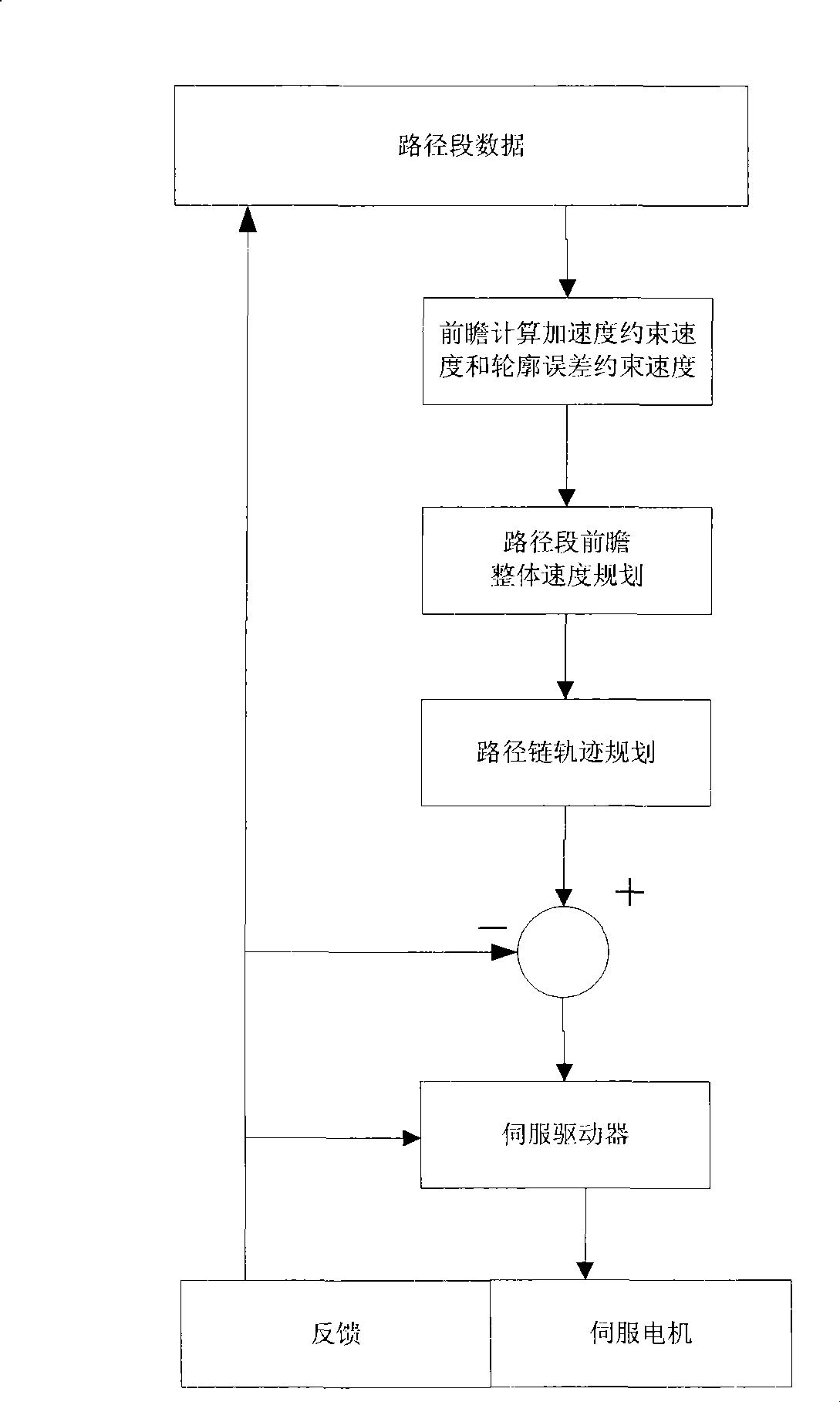
[0054] In this embodiment, the hardware platform adopts full digital control mode, standard industrial grade IPC board card, PM-1GHz CPU as the numerical control system controller, and the axis adopts MECHATROLINK bus control mode. The open numerical control system developed on the basis of this platform is an integrated numerical control system, giving full play to its characteristics of fast calculation speed and powerful functions, and completes functions such as display, interpolation calculation, and motion control through software. In this CNC system, the motion controller is the core. After adopting the speed forward control method based on filtering technology, the component structure of the motion controller is as follows: figure 1 shown.

[0055] The method of the present invention is based on the acceleration and deceleration characteristics of the filtering tec...


PUM


Abstract

The invention relates to a look-ahead velocity control method based on filtering technique, which comprises steps of linking path segments of a processing curve into a path chain, prospectively calculating a constraint velocity for a maximum acceleration and a constraint velocity for the profile error at the corner of the processing curve, operating the corner velocity according to each constraint velocity, prospectively planning the integral velocity of the path chain through the linear accelerating and decelerating strategy to obtain a prospectively planned velocity of the path chain, and utilizing a differential value between the corner velocity and the path chain prospectively planned velocity as a criterion to judge whether decelerating in advance or not during the interpolation procedure, if the differential value is out of a stated threshold value, then calculating the length of the decelerating segments in the path chain, reversely recursing the decelerating path segments in the path chain to set the required feeding velocity, performing track planning to the path chain , and realizing self-adaptive adjustment of the processing velocity along with geometric configuration changes of processing paths through adjusting the required feeding velocity of the decelerating path segments. The look-ahead velocity control method has the advantages of high flexible self-adapting control capacity, high executing efficiency, good velocity smoothness and the like.

Description

technical field [0001] The invention relates to the speed control technology of a numerical control system, in particular to a speed forward control method based on filtering technology for processing complex paths. Background technique [0002] In the NC machining of complex curved surfaces, the post-processor of the CAD / CAM system approximates the complex path with a series of small path segments composed of straight lines or arcs with an allowable error, and then the CNC system performs each path segment Interpolation operation. In order to realize high-speed machining, the feed speed of the tool along the contour surface of the workpiece is required to be greatly increased, and a large number of small path segments need to be traversed in a short time. At this time, if the control is carried out according to the conventional speed control method, and each path segment is used to perform three-stage movement of acceleration, constant speed, and deceleration, since the pa...

Claims


Application Information

Patent Timeline
Patent Type & Authority Applications(China)
IPC IPC(8): G05B19/4097
Inventor 于东张晓辉杜少华宋桃桃胡毅
Owner SHENYANG GOLDING NC & INTELLIGENCE TECH CO LTD
Why Eureka
Try Eureka