An antenna

An antenna and antenna radiation technology, applied in the direction of antenna, resonant antenna, antenna support/installation device, etc., can solve the problems of large device loss, low antenna gain, low radiation impedance, etc., to overcome power loss and reduce antenna resonance frequency , The effect of reducing the size of the antenna

Inactive Publication Date: 2009-07-01
联想(上海)有限公司
View PDF0 Cites 15 Cited by
  • Summary
  • Abstract
  • Description
  • Claims
  • Application Information

AI Technical Summary

Problems solved by technology

[0004] Using capacitance or inductance as loading can reduce the size of the antenna, but the device loss is relatively large at mobile communication frequencies (above 800MHz), resulting in a lower actual gain of the antenna; folding the vibrator can reduce the electrical size, but using a folding vibrator on the edge of the notebook The vibrator, because the radiator is very close to the metal frame of the notebook, the radiation space is very limited, the radiation impedance is very low, it is not easy to match the impedance, and the antenna bandwidth is narrow; although slotting and slits can reduce the electrical size of the antenna, the antenna needs to be installed on the notebook At the edge of the screen, there is often not enough space for slots and slits

Method used


Image

  • An antenna
  • An antenna
  • An antenna

Examples


Embodiment Construction

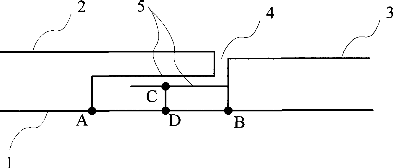
[0037] The invention adopts the coupling between the radiation branches of the antenna to form capacitance, thereby reducing elements and isolation space, reducing the size of the antenna, and making the antenna more suitable for the size requirement of portable devices.

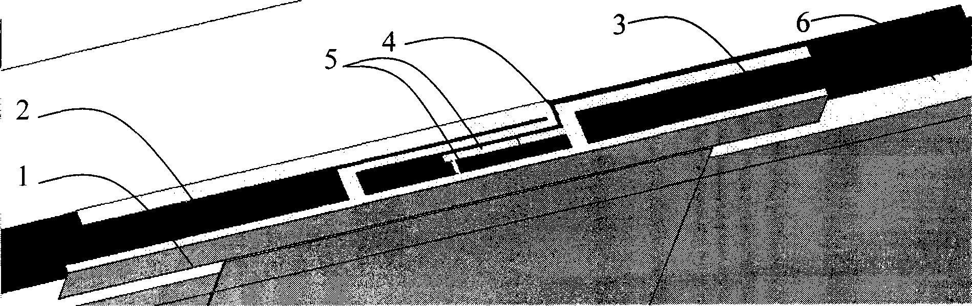
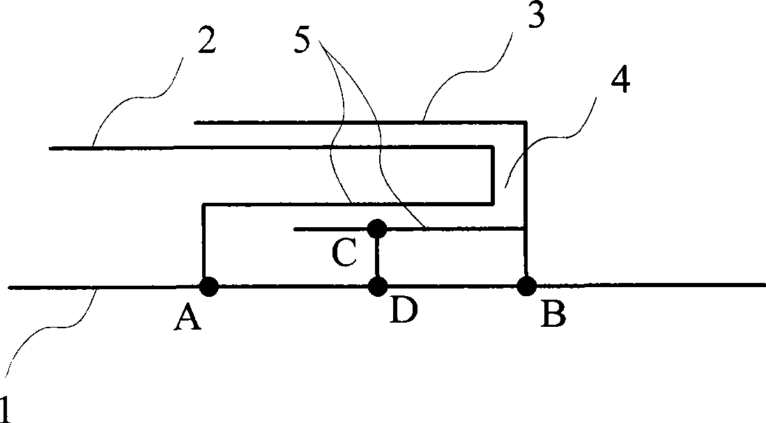
[0038] figure 1 is a structural schematic diagram of the first embodiment of the present invention, such as figure 1 As shown, the coplanar waveguide coupled dual-frequency antenna consists of a reference ground 1, a coplanar waveguide coupled radiation branch 2 and a planar inverted F antenna (Pifa, PlanarInverted F Antenna) radiation branch 3. Wherein, the reference ground 1 is a planar metal with a narrow strip structure; the coplanar waveguide coupling radiation branch 2 is a zigzag narrow strip metal sheet, one end is parallel to the reference ground 1, and the connection point between the other end and the reference ground 1 is the grounding point A; The Pifa radiation branch 3 is a T-shaped metal she...


PUM


Abstract

The invention relates to an antenna, which comprises a reference ground, a first radiation branch and a second radiation branch, wherein the reference ground includes a first grounding point and a second grounding point; the first radiation branch is connected with the reference ground through the first grounding point; the second radiation branch is connected with the reference ground through the second grounding point; a slit is formed between the first radiation branch and the second radiation branch, and the first radiation branch and the second radiation branch are coupled with each other through the slit to form a distributed capacitance for signal coupling; and the connection point between one end of the second radiation branch for signal coupling and an RF feed line services as a feed point, which is located between the first grounding point and the second grounding point. The antenna has the advantages that a coplanar waveguide coupling structure between the resonant branches of the antenna is equivalent to capacitor loading, and the field loaded by the distributed capacitance is mainly centralized in the air, so that power loss caused by internal resistance of the device loaded with a lumped parameter capacitor is obviated, thereby lowering the resonant frequency of the antenna and reducing the antenna size.

Description

technical field [0001] The invention relates to the antenna technology of a communication terminal, in particular to an antenna. Background technique [0002] Using a multi-antenna system on a notebook requires installing multiple antenna units at the same time, but the space where the antenna units can be installed is limited, and the distance between the antenna units must be kept sufficient to reduce coupling, so the space that each antenna unit can occupy must not be limited. Do not shrink. Generally, the notebook antennas are installed on the edge of the machine in a long strip shape. Generally, the size of the antenna unit is required to be about a quarter of the wavelength. In this way, in the 900MHz GSM frequency band, the antenna unit should be about 80-90mm. The distance between the antenna units should be greater than one-third of the wavelength, that is, 110mm, and about 270mm is required to install two antenna units. And considering that other frequency bands...

Claims


Application Information

Patent Timeline
Patent Type & Authority Applications(China)
IPC IPC(8): H01Q1/22H01Q1/36H01Q13/08
CPCH01Q9/42H01Q5/0062H01Q5/378
Inventor 颜罡张孝林范丽莉崔斌
Owner 联想(上海)有限公司
Why Eureka
Try Eureka