
Piezoelectric clamping device

A clamping device and piezoelectric technology, applied in the direction of electromechanical devices, electrical components, electric components, etc., can solve problems such as complex hardware implementation, achieve long-stroke driving effects, and improve the effect of clamping force

Active Publication Date: 2009-07-01
METAL INDS RES & DEV CENT
View PDF0 Cites 1 Cited by
  • Summary
  • Abstract
  • Description
  • Claims
  • Application Information

AI Technical Summary

Problems solved by technology

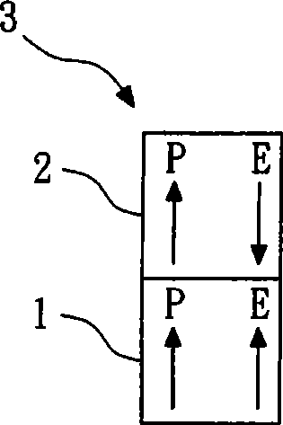
[0009] The driving method of the above-mentioned conventional stacked piezoelectric driver 3 is the most common and most convenient method among precision piezoelectric drivers, but relatively two kinds of piezoelectric materials need to be used, and they need to be matched accurately Two-phase electrical signals (the first drive signal and the second drive signal) can produce a better motion trajectory, and its hardware implementation is more complicated

Method used


Image

  • Piezoelectric clamping device
  • Piezoelectric clamping device
  • Piezoelectric clamping device

Examples


Embodiment Construction

[0033] Figure 5 A perspective view showing the piezoelectric clamping device of the first embodiment of the present invention; Figure 6 A sectional view showing the piezoelectric clamping device of the first embodiment of the present invention; Figure 7 A schematic diagram showing the driving element disposed on the piezoelectric element according to the first embodiment of the present invention. combined reference Figure 5 , Figure 6 and Figure 7 , the piezoelectric clamping device 4 of the first embodiment includes: a base 41, a clamping unit 42, a driving element 43, at least one piezoelectric element 44 (three in this embodiment) and a prestressing device 45 . The base 41 has a first side 411 . The clamping unit 42 has a first clamping element 421 and a second clamping element 422, the first clamping element 421 is arranged on the first side 411 of the base 41, the second clamping The holding element 422 is relative to the first holding element 421. Preferabl...


PUM


Abstract

The invention relates to a piezoelectric holding device which utilizes at least one piezoelectric element for driving a drive element and further driving a holder to achieve the holding effect. The piezoelectric holding device utilizes the prestressing force which is applied onto the drive element by a prestressing device to simultaneously limit the unexpectable vertical and horizontal deviations of the drive element. In addition, the drive element can realize the effects of long drive and high holding force of the drive element through a plurality of deformations of the piezoelectric element.

Description

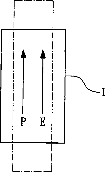
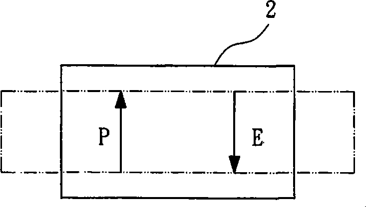
technical field [0001] The present invention relates to a clamping device, in particular to a piezoelectric clamping device. Background technique [0002] The micro-gripper (Micro-Gripper) plays a very important key core in the micro-assembly system, and the micro-drive device is an important technical module that is related to the quality of the pick-and-place. When it comes to micro-driving devices or precision driving devices, it is nothing more than using the micro-deformation characteristics of piezoelectric elements to achieve. According to the difference between the polarization direction (P) of the material and the direction (E) of the applied electric field, common piezoelectric elements often use the longitudinal effect and the transverse effect as the driving method (that is, the horizontal and vertical configurations, although in fact the longitudinal effect and the transverse effect effect as the driving method, but from the perspective of deformation, both ver...

Claims


Application Information

Patent Timeline
Patent Type & Authority Applications(China)
IPC IPC(8): H02N2/00H02K15/00
Inventor 薛博文蔡明祺林忠宪吴永成王圣禾
Owner METAL INDS RES & DEV CENT
Learn More