Dust collector

A technology of dust collection device and dust collection part, which is applied in the direction of external electrostatic separator, solid separation, electrostatic separation, etc., can solve the problems such as difficulty in miniaturization of the device, difficulty in achieving high performance, small dust collection area, etc., and achieve the goal of Miniaturization, high performance, and increased dust collection area

Active Publication Date: 2009-07-01
DAIKIN IND LTD
View PDF0 Cites 11 Cited by
  • Summary
  • Abstract
  • Description
  • Claims
  • Application Information

AI Technical Summary

Problems solved by technology

[0005] However, in the conventional dust collecting device, although the dust collecting electrode and the high voltage electrode of the dust collecting part are made of resin, they are parallel flat plates. Therefore, there is a problem that it is difficult to reduce the size of the device, and it is also difficult to achieve high performance.
That is to say, since the dust collecting electrodes are only configured as flat plates and simply arranged in parallel, there is a problem that the dust collecting area in a certain space as a dust collecting device is small.
As a result, in order to ensure a certain dust collection capacity, the size of the device will be enlarged and the performance will be low.

Method used


Image

  • Dust collector
  • Dust collector
  • Dust collector

Examples


no. 1 approach

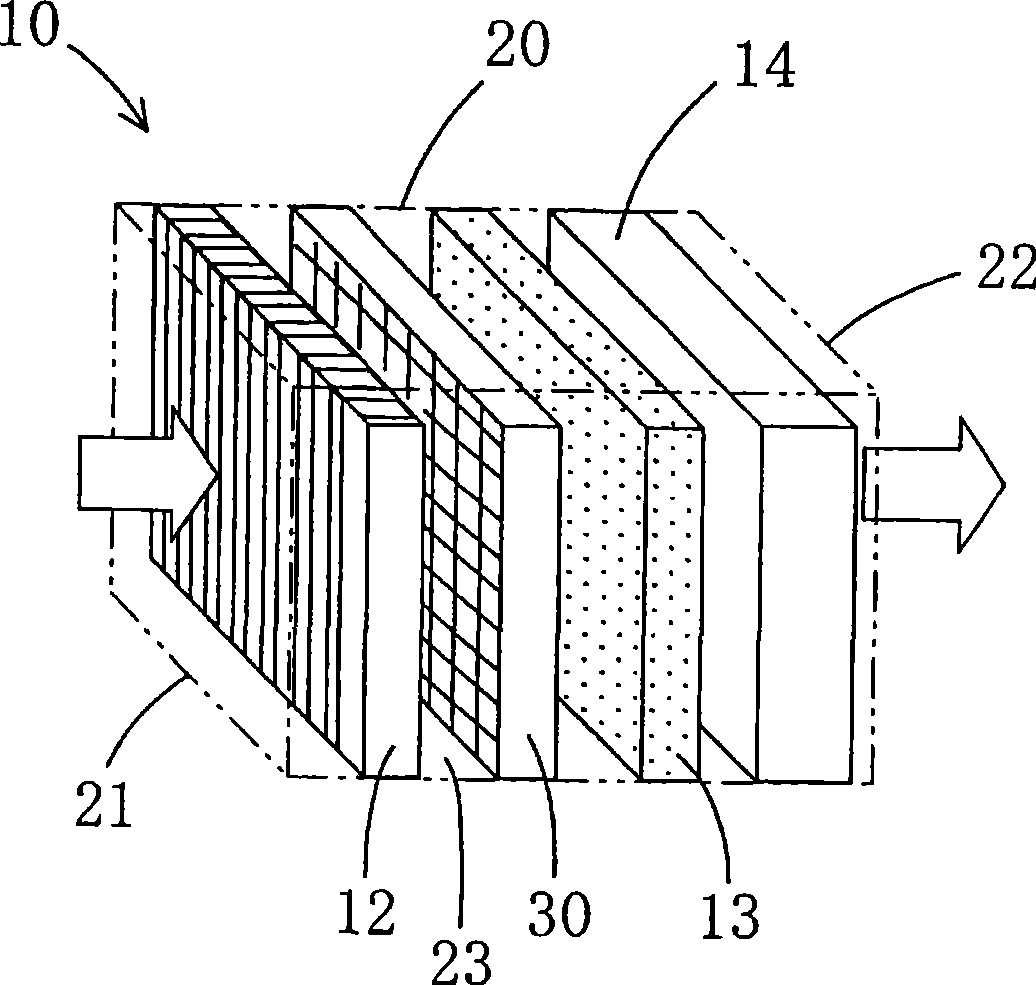
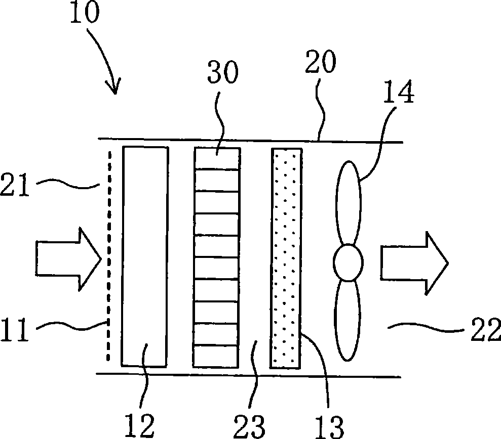
[0079] like figure 1 and figure 2 As shown, the air cleaner 10 in this embodiment constitutes the dust collecting device of the present invention, and is, for example, a domestic air cleaning device used in general households, small-scale stores, and the like.

[0080] The above-mentioned air cleaner 10 includes a housing 20 , and includes a preliminary filter 11 installed inside the housing 20 , a charging unit 12 , a dust collecting unit 30 , a catalyst filter 13 and a fan 14 .

[0081] The casing 20 is formed, for example, as a rectangular parallelepiped long container with an air inlet 21 on the front, an air outlet 22 on the back, and an air passage 23 inside. The preliminary filter 11 , charging unit 12 , dust collecting unit 30 , catalyst filter 13 , and fan 14 are arranged in order from the suction port 21 to the blowing port 22 .

[0082] The preliminary filter 11 constitutes a filter for trapping relatively large dust contained in the air sucked into the casing 20...

no. 2 approach

[0117] Next, a second embodiment of the present invention will be described in detail with reference to the drawings.

[0118] like Image 6 As shown, in this embodiment, the dust collecting electrode 40 is made of conductive metal instead of both the dust collecting electrode 40 and the high voltage electrode 50 being made of conductive resin in the first embodiment.

[0119] That is, the dust collecting electrode 40 is formed of a thin metal plate such as stainless steel, and the high voltage electrode 50 is formed of a conductive resin as in the first embodiment.

[0120] Like the first embodiment, the dust collecting electrode 40 is formed in a rectangular shape and includes a base part 41 and many protruding parts 42. Isolation part 45. Furthermore, the protruding member 42, the frame body 43, the vertical spacer 44, and the horizontal spacer 45 are each formed of a thin conductive metal plate.

[0121] As in the first embodiment, the protruding part 42 of the dust col...

no. 3 approach

[0125] Next, a third embodiment of the present invention will be described in detail with reference to the drawings.

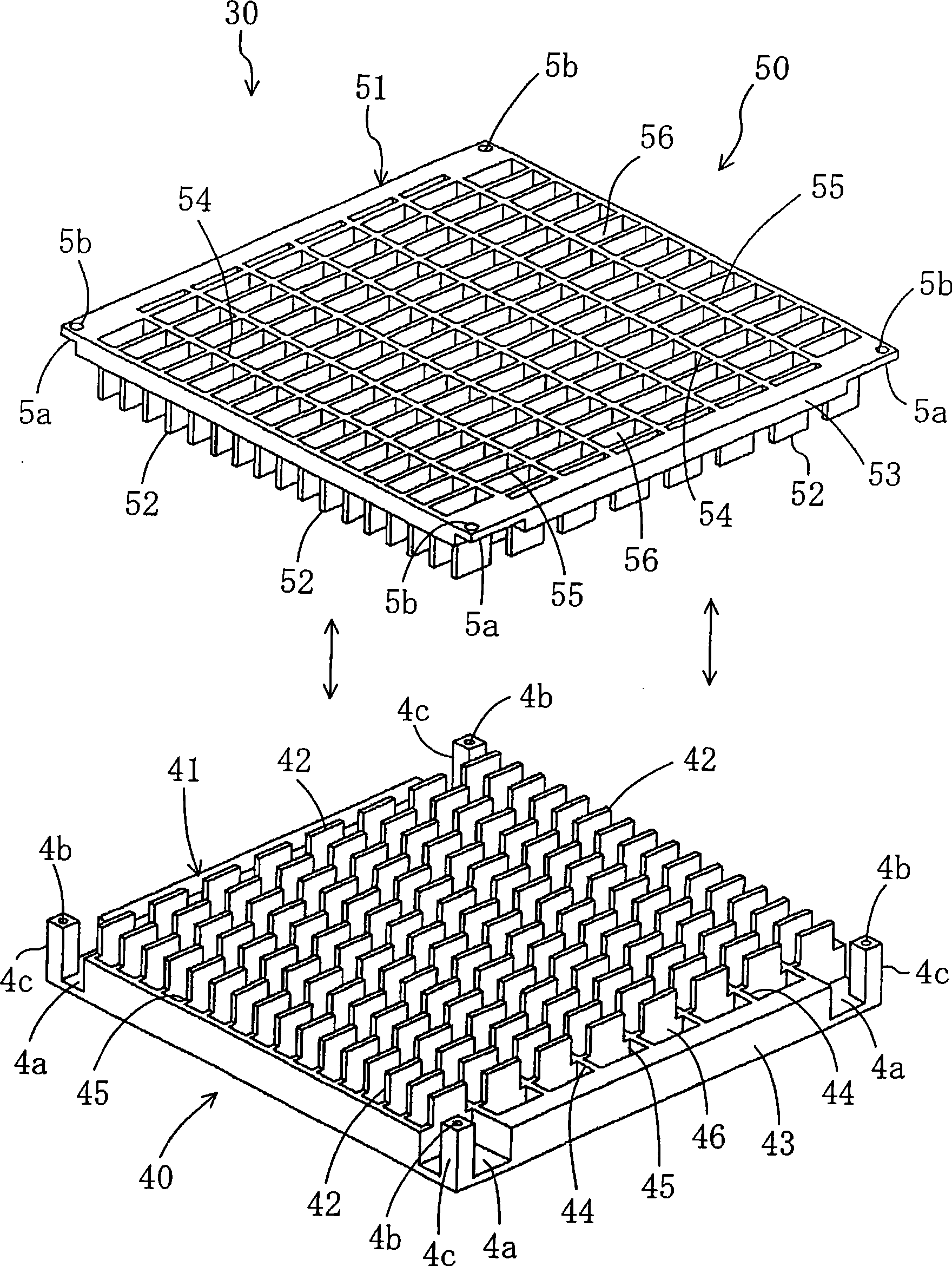
[0126] like Figure 7 and Figure 8 As shown, this embodiment is a structure in which only the high-voltage electrode 50 is embedded in the dust-collecting electrode 40 , replacing the structure in which the dust-collecting electrode 40 and the high-voltage electrode 50 are embedded in each other in the first embodiment.

[0127] That is, the dust collecting electrode 40 is formed in a rectangular shape and includes one base member 41 . The base member 41 includes a frame body 43 , a plurality of vertical partition members 44 , and a plurality of horizontal partition members 45 . Therefore, the dust collecting electrode 40 in this embodiment does not include many protruding parts 42 in the first embodiment, and the dust collecting electrode 40 is formed in a simple lattice structure.

[0128] On the other hand, like the first embodiment, the high-voltage el...


PUM


Abstract

A dust collector includes a charging part (12) for charging dust with electricity and a dust collecting part (30). Each of a dust collecting electrode (40) and a high-voltage electrode (50) that constitute the dust collecting part (30) includes: a base (41, 51) with a rectangular grid structure having a large number of vent holes (46, 56) formed therein; and projections (42, 52) extending into the vent holes (56, 46) of the opposed electrode (50, 40). The dust collector collects dust by generating an electric field between the dust collecting electrode (40) and the high-voltage electrode (50).

Description

technical field [0001] The invention relates to a dust collecting device, in particular to an electrode structure. Background technique [0002] Conventionally, as disclosed in Patent Document 1, some of the dust collectors include a charging unit for charging dust, and a dust collecting unit having a dust collecting electrode and a high voltage electrode. The dust-collecting electrode and the high-voltage electrode of the dust-collecting part are composed of parallel plates, and the dust-collecting electrode is inserted between the high-voltage electrodes. [0003] The above-mentioned dust collecting device charges the dust in the air at the charging part, and generates an electric field between the dust collecting electrode and the high voltage electrode, and collects the dust charged at the charging part at the dust collecting part. [0004] Patent Document 1: Japanese Patent Laid-Open Publication No. 8-71451 [0005] However, in the conventional dust collecting device,...

Claims


Application Information

Patent Timeline
Patent Type & Authority Applications(China)
IPC IPC(8): B03C3/47B03C3/64
CPCB03C3/09B03C3/41B03C3/51B03C3/47B03C2201/10B03C3/12B03C3/08B03C3/64
Inventor 田中利夫茂木完治秋山龙司大堂维大春名俊治
Owner DAIKIN IND LTD
Why Eureka
Try Eureka