Photoelectrocatalysis air cleaning device having turbulence air channel

An air purification device and photoelectric catalysis technology, which is applied in public health, medical care, automobiles, and household fields, can solve the problems of reducing purification efficiency, secondary dust, and loud noise, so as to reduce energy consumption, improve purification efficiency, and rationally use space Effect

Inactive Publication Date: 2011-07-13
KINGBY PHOTOCATALYSIS SCI & TECH
View PDF7 Cites 3 Cited by
  • Summary
  • Abstract
  • Description
  • Claims
  • Application Information

AI Technical Summary

Problems solved by technology

[0003] Since the dust collection and purification components have a certain wind resistance, the higher the purification efficiency is, the greater the wind resistance will be. Therefore, in order to obtain greater purification efficiency, the power of the motor must be increased to obtain a relatively high purification efficiency. Increased, the wind resistance increases and also produces a relatively large noise
For air purifiers using electrostatic dust collection technology, if the wind speed is too high, it is easy to generate secondary dust and reduce the purification efficiency
[0004] Regardless of whether a cross-flow fan, an axial-flow fan or a cross-flow fan is used, the air duct takes up a lot of space, and the purifier products composed of the air duct and the dust collection and purification module are generally relatively large in size and low in efficiency, which also affects the purifier. The technical development of the product has brought constraints
[0005] However, due to the diversity of air pollution types and the complexity of air components, the common pollution types in the air such as PM10, microbial virus bacteria, odor, TVOC and other pollutants are known, and traditional purification technologies can usually only target one of them. A variety of pollutants, unable to achieve comprehensive purification of multiple pollutants at the same time

Method used


Image

  • Photoelectrocatalysis air cleaning device having turbulence air channel
  • Photoelectrocatalysis air cleaning device having turbulence air channel
  • Photoelectrocatalysis air cleaning device having turbulence air channel

Examples


Embodiment Construction

[0033] Below in conjunction with accompanying drawing, the patent of the present invention is further described.

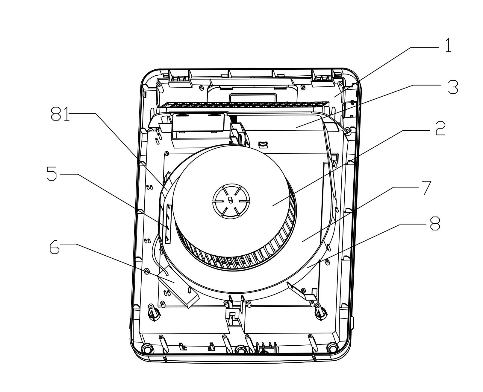
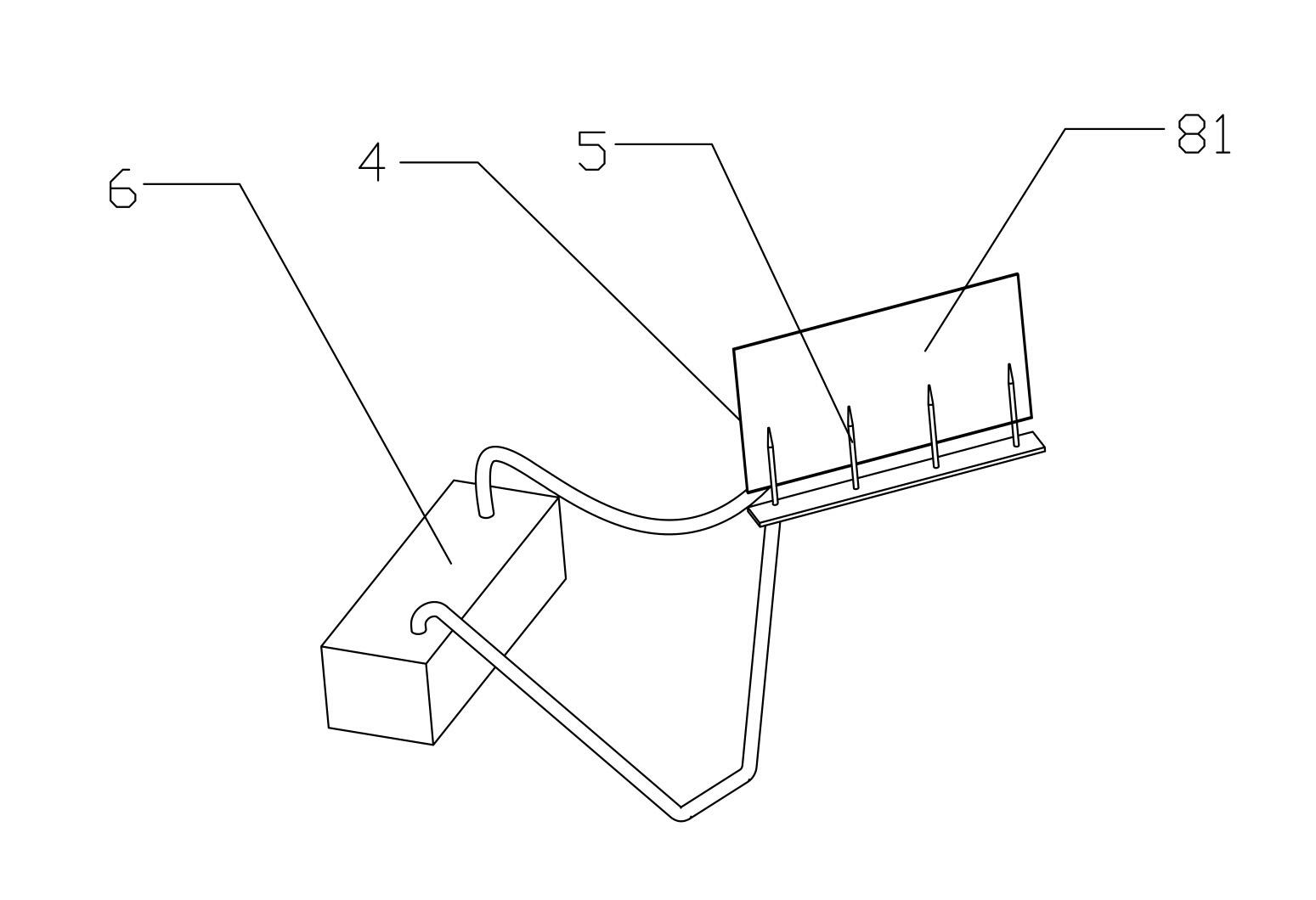
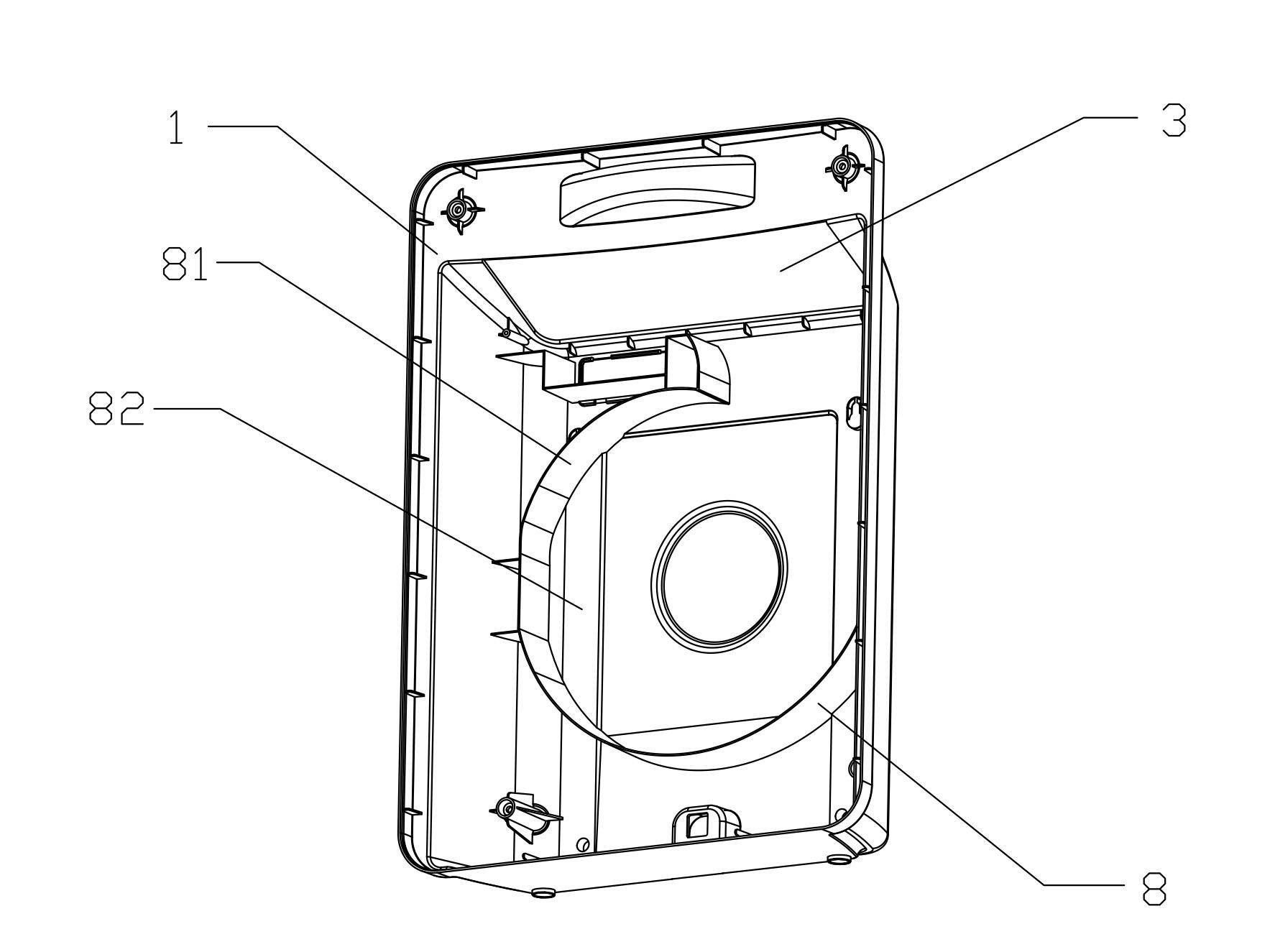
[0034] according to figure 1 , figure 2 , image 3 , Figure 4 , Figure 5 , Image 6 , Figure 7 , Figure 8 , Figure 9 and Figure 10 As shown, the photoelectric catalytic air purification device with turbulent air duct described in the patent of the present invention includes a housing 1, an air supply mechanism 2 and an arc-shaped air duct 7 arranged on the housing 1, and the housing 1 is provided with an outlet Tuyere 3. Wherein, the air supply mechanism 2 is connected with the air outlet 3 through the arc-shaped air duct 7, and the arc-shaped air duct 7 is equipped with a corona emitter 5, and the inner wall surface 8 of the corona emitter 5 and the arc-shaped air duct 7 is connected to the power supply 6 respectively. Electrically connected, the power supply 6 is preferably a power supply of 10000-30000 volts, specifically a positive high-voltag...


PUM


Abstract

The invention discloses a photoelectrocatalysis air cleaning device having a turbulence air channel, which comprises a shell and an air-blowing mechanism arranged on the shell, wherein an air outlet is arranged on the shell; the air-blowing mechanism is connected to the air outlet through an arc-shaped air channel; the arc-shaped air channel is the arc-shaped air channel part in the air-blowing mechanism; a corona emitter electrode is arranged on the arc-shaped air channel; the corona emitter electrode and the inner wall of the arc-shaped air channel are respectively electrically connected to a power supply; a photoelectrocatalysis layer is coated on the inner wall of the arc-shaped air channel; and a dust-collecting cleaning wall is formed by the inner wall of the arc-shaped air channel under the condition of an electric field. The photoelectrocatalysis air cleaning device has reasonable space distribution, has large dust-collecting area, is high in cleaning efficiency, has wide cleaning scope, is low in air resistance and is small in energy consumption.

Description

technical field [0001] The patent of the present invention relates to a photocatalytic air purification device, in particular to a new generation of air purifier with a photocatalytic air purification device with a turbulent air duct, which is suitable for household, automobile, medical treatment, public health and other fields. Background technique [0002] At present, the existing purifiers mainly have the following methods: adsorption type, electrostatic type, etc. The above purification methods usually adopt the method that the air supply mechanism and the dust collection and purification components are independent modules and combined, the air supply mechanism Cross-flow, axial-flow, and cross-flow fans can be used to bring the polluted air through the dust collection assembly, and the dust collection and purification assembly intercepts the pollutants in the air, so the air is purified. [0003] Since the dust collection and purification components have a certain win...

Claims


Application Information

Patent Timeline
Patent Type & Authority Applications(China)
IPC IPC(8): A61L9/00A61L9/18F24F3/16A61L101/02
Inventor 袁伟雄
Owner KINGBY PHOTOCATALYSIS SCI & TECH
Why Eureka
Try Eureka