Power switching circuit and power switching method thereof

A power switching and power supply technology, applied in circuit devices, emergency power supply arrangements, electrical components, etc., can solve problems such as overall performance reduction, multi-memory space, development and execution difficulties, etc., to achieve the effect of improving overall performance and reducing system resource consumption

Active Publication Date: 2013-06-05
UNIVERSAL SCIENTIFIC INDUSTRIAL (SHANGHAI) CO LTD +1
View PDF6 Cites 15 Cited by
  • Summary
  • Abstract
  • Description
  • Claims
  • Application Information

AI Technical Summary

Problems solved by technology

[0004] However, when the existing power management system starts the first power supply 101, the first power supply 101 supplies power to the load 104, and the instantaneous inrush current will damage the electronic device at the load 104 end.
In addition, using software to control the power management system to switch power sources will occupy part of the memory space of the power management system and consume the working time of the microprocessor, reducing the overall performance.
For example, in a digital camera, in addition to using the database program to manage the archive and the image program to manage the lens in the memory, if the power management program is also used to manage the power supply, it will undoubtedly take up more memory space. While the microprocessor is processing multiple programs, the power management program will also occupy part of the working time of the microprocessor and cause other programs to respond slowly
In detail, when the power management system 100 is connected to a notebook computer to supply power to a mobile phone, and uses the USB interface for data transmission, in addition to managing data transmission, it also needs to take into account the charging function. Therefore, the software of the power management system 100 The complexity of program design is high, and it will be more difficult to develop and execute, not to mention that there are more programs executing at the same time in the laptop, the power management program will consume system resources, and the impact on other programs will be more significant

Method used


Image

  • Power switching circuit and power switching method thereof
  • Power switching circuit and power switching method thereof
  • Power switching circuit and power switching method thereof

Examples


Embodiment Construction

[0039] The preferred embodiments of the present invention are given below in conjunction with the accompanying drawings to describe the technical solution of the present invention in detail.

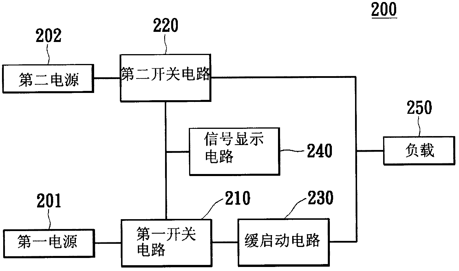
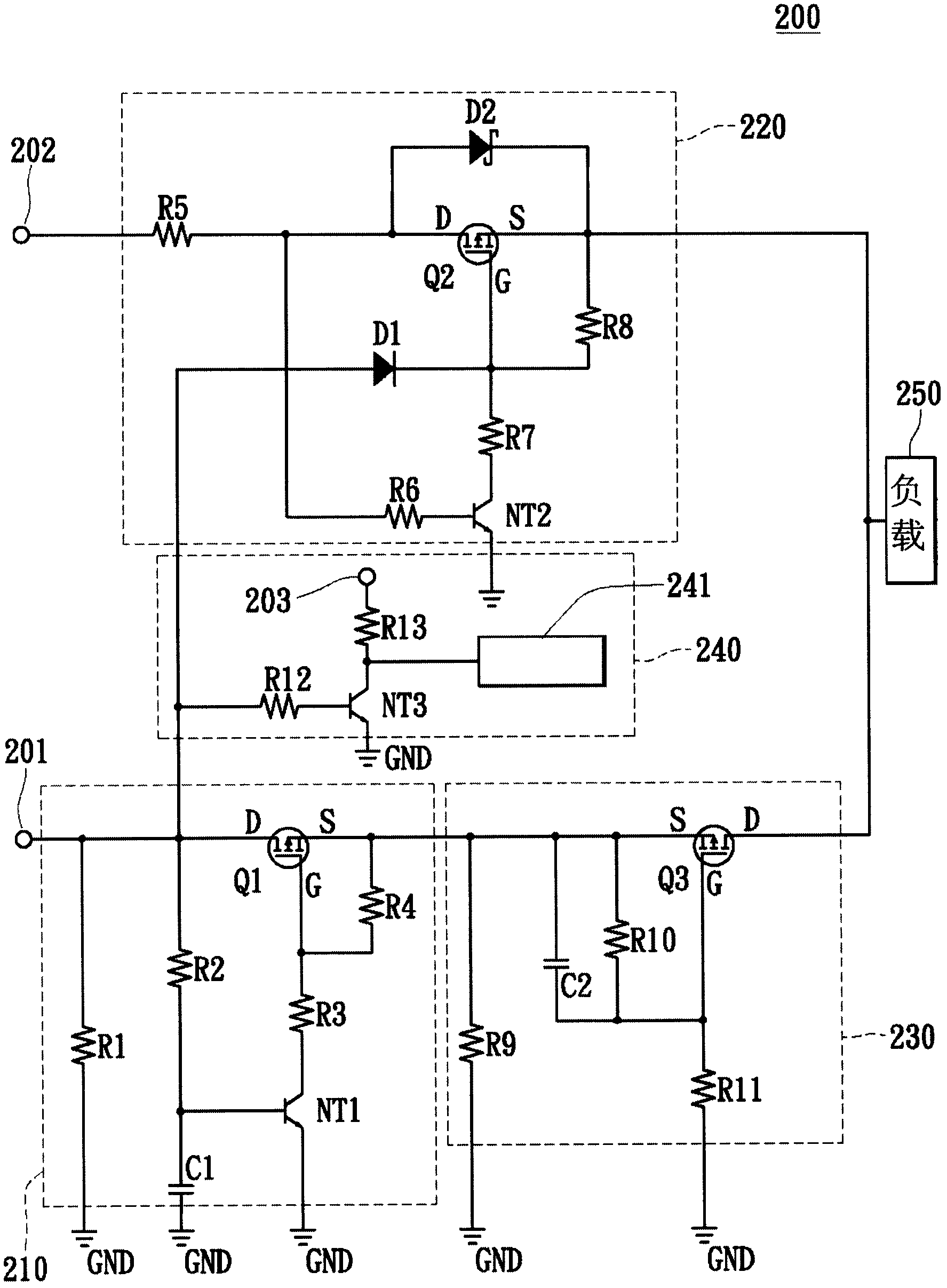
[0040] figure 2 It is a block diagram of a power switching circuit of a preferred embodiment of the present invention. The power switch circuit 200 includes a first switch circuit 210 , a second switch circuit 220 , a slow start circuit 230 , a signal display circuit 240 and a load 250 . The power switch circuit 200 is coupled between the first power source 201 , the second power source 202 and the load 250 for switching the first power source 201 and the second power source 202 to supply power to the load 250 . The first power supply 201 and the second power supply 202 are, for example, direct current power supplies for outputting voltage and current, and can supply power independently or the first power supply 201 and the second power supply 202 can switch power supplies for the same...


PUM


Abstract

The invention discloses a power switching circuit and a power switching method thereof. The power switching circuit comprises a first switching circuit, a second switching circuit and a slow starting circuit. The first switching circuit is coupled with a first power supply end, and breakover or turnoff is determined according to the voltage level of the first power supply end. The second switching circuit is coupled among the first switching circuit, a second power supply end and load, and breakover or turnoff is determined according to the voltage level of a power supply and a second power supply. The slow starting circuit is coupled between the first switching circuit and the load. When the voltage level of the first power supply end is larger than a preset value, breakover of the first switching circuit and turnoff of the second switching circuit are achieved. When the voltage level of the first power supply end is lower than the preset value, turnoff of the first switching circuit and breakover of the second switching circuit are achieved, and breakover of the slow starting circuit is achieved after the breakover of the first switching circuit lasts for a preset time. According to the power switching circuit and the power switching method, power supply management is achieved through a hardware circuit design mode, and resource consumption is further reduced.

Description

technical field [0001] The invention relates to a power switching circuit, in particular to a power switching circuit for preventing instantaneous inrush current and a power switching method realized by using the power switching circuit. Background technique [0002] With the rapid development of science and technology in recent years, the types and output of electronic products are also increasing, such as notebook computers, wireless sharers, PDAs (handheld computers), digital cameras, and mobile phones. In the design of on chip (SOC), in order to effectively use the power supply, the dual power design (dual power) is widely used in various electronic devices. [0003] Please refer to figure 1 , showing a structure diagram of a power management system 100 with a dual power supply design. The power management system 100 includes a first power source 101 , a second power source 102 , a power switching circuit 103 and a load 104 . Wherein, when the first power source exist...

Claims


Application Information

Patent Timeline
Patent Type & Authority Applications(China)
IPC IPC(8): H02J9/04
Inventor 洪榆棍王文宏黄威翔
Owner UNIVERSAL SCIENTIFIC INDUSTRIAL (SHANGHAI) CO LTD
Why Eureka
Try Eureka