Tensioning device for a traction mechanism, in particular a belt or a chain

A technology of tensioning device and traction mechanism, applied in belt/chain/gear, transmission, mechanical equipment, etc., can solve problems such as noise and vibration

Inactive Publication Date: 2009-07-01
SCHAEFFLER TECH AG & CO KG
View PDF1 Cites 3 Cited by
  • Summary
  • Abstract
  • Description
  • Claims
  • Application Information

AI Technical Summary

Problems solved by technology

When the stop is not abutted, the spring strip is therefore also not under tension and is therefore movable, so that it can vibrate, which may lead to noise formation

Method used


Image

  • Tensioning device for a traction mechanism, in particular a belt or a chain
  • Tensioning device for a traction mechanism, in particular a belt or a chain
  • Tensioning device for a traction mechanism, in particular a belt or a chain

Examples


Embodiment Construction

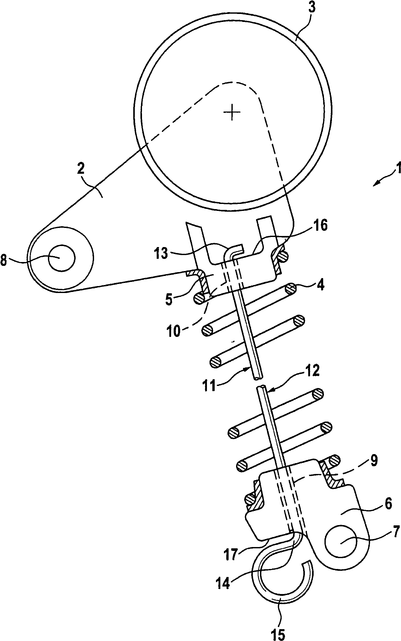
[0018] figure 1 A tensioning device 1 according to the invention is shown, said device 1 comprising a tensioning rod 2 on which a tensioning roller 3 is arranged here, by means of which the traction mechanism is guided in the assembled position, Especially for guiding the belt. Furthermore, the tensioning device 1 comprises a tensioning spring 4 which is here embodied as a helical spring and rests with its end facing the tensioning rod 2 on a spring support 5 which is connected to the tensioning spring 5 . The rod 2 is firmly connected or is part of the tension rod 2 . The other end of the tension spring 4 is placed on the spring holder 6 . The spring carrier 6 is fastened to a third object, for example a motor vehicle engine or the like, for which fastening holes 7 are used, via which the tensioning device is pivotally mounted there. In a corresponding manner, the tensioning lever 2 also has fastening holes 8 , by means of which the tensioning lever 2 can be pivotably fast...


PUM


Abstract

The invention relates to a tensioning device for a traction mechanism, in particular a belt or a chain, comprising a lever arm (2, 19) over which the traction mechanism is guided and on which a tensioning spring is arranged with its one end, the other end of which tensioning spring is arranged on a spring holder (6, 21), by means of which the tensioning device (1, 18, 30) can be fastened to an external object, wherein a holding element (11, 22, 34), which extends from the lever arm (2, 19) to the spring holder (6, 21) and is detachably arranged on both said lever arm (2, 19) and said spring holder (6, 21), for holding the tensioning device (1, 18, 30) in a position with a preloaded tensioning spring (4, 20, 33) is provided.

Description

technical field [0001] The invention relates to a tensioning device for a traction mechanism, in particular for a belt or a chain, said tensioning device comprising a lever arm via which the traction mechanism is guided and a tensioning spring with one end The other end of the tensioning spring is arranged on a spring mount, by means of which the tensioning device can be fixed on a third object. Background technique [0002] Such a tensioning device is known, for example, from DE 195 01 685 C1. In order to simplify the assembly of such a tensioning device, the tensioning device presented here has a tension-absorbing connecting element in the form of a spring strap, which extends from the spring carrier to the lever arm, wherein between the two Tension springs are arranged between them in a known manner. The lower end of the spring strip is positioned on the spring support by pins inserted into the socket holes. The spring strip passes through the tensioning spring inside ...

Claims


Application Information

Patent Timeline
IPC IPC(8): F16H7/12F16H7/08
CPCF16H2007/0878F16H7/1281F16H2007/0806F16H2007/0893F16H7/12F16H7/08
Inventor 赫尔曼·施蒂夫米夏埃尔·伯格纳
Owner SCHAEFFLER TECH AG & CO KG
Why Eureka
Try Eureka