
Radio resource allocation method and radio base station

A technology of wireless resources and wireless base stations, applied in wireless communication, electrical components, etc., can solve problems such as the effect of intermittent reception that cannot be expected

Inactive Publication Date: 2009-07-01
NTT DOCOMO INC
View PDF1 Cites 2 Cited by
  • Summary
  • Abstract
  • Description
  • Claims
  • Application Information

AI Technical Summary

Problems solved by technology

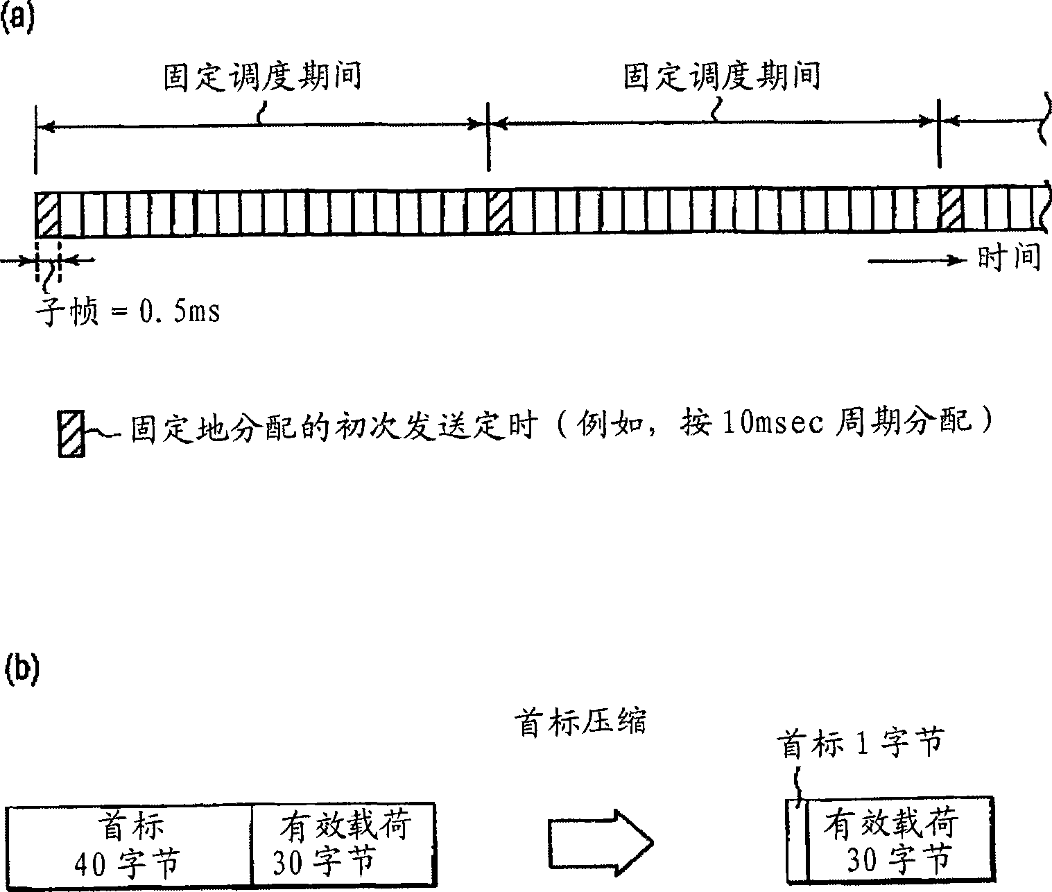
Therefore, if fixed scheduling and dynamic scheduling are simply used together, the effect of intermittent reception cannot be expected

Method used


Image

  • Radio resource allocation method and radio base station
  • Radio resource allocation method and radio base station
  • Radio resource allocation method and radio base station

Examples


Embodiment Construction

[0034] Hereinafter, preferred embodiments of the present invention will be described with reference to the drawings.

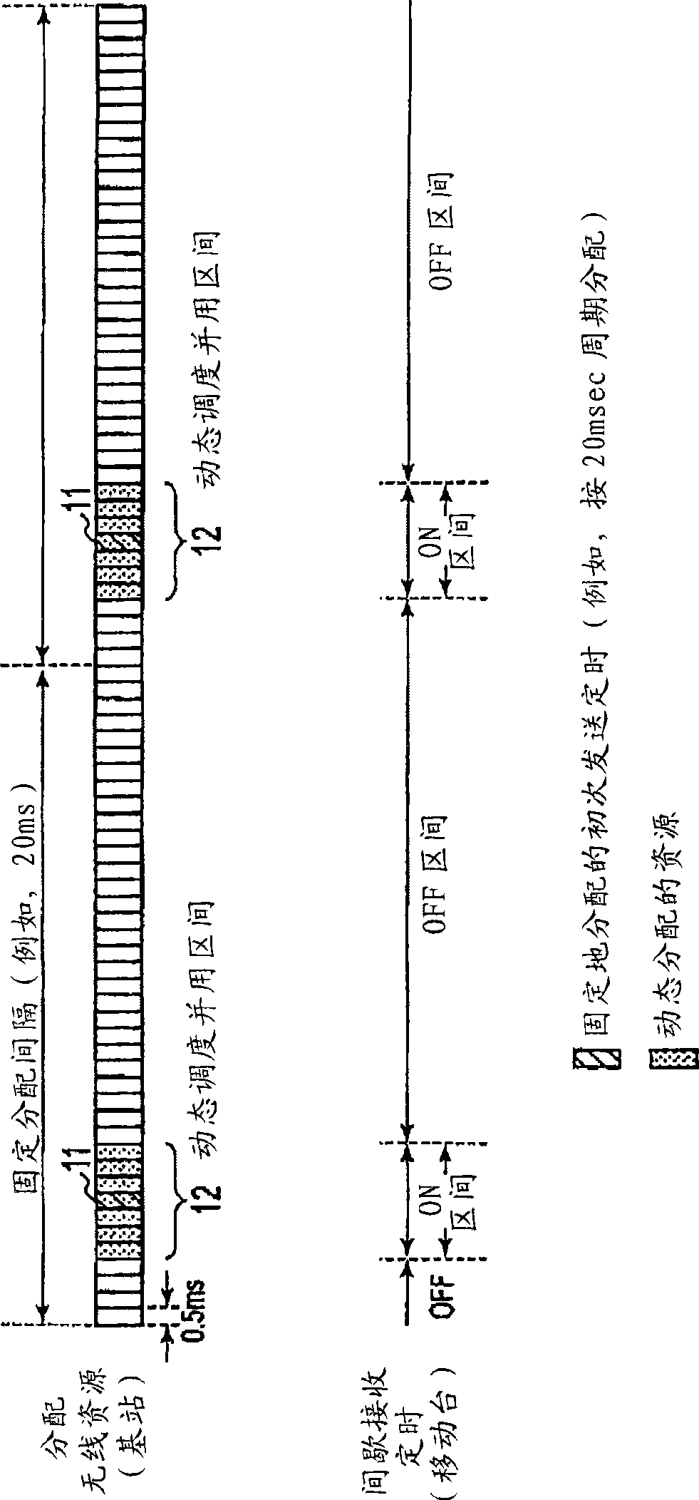
[0035] figure 2 It is a diagram for explaining a radio resource allocation method according to an embodiment of the present invention.

[0036] exist figure 2 In the example of , the period during which fixed scheduling is performed (fixed scheduling period) is set to "20ms". That is, it is assumed that voice traffic such as VoIP packets exists every 20 ms.

[0037] One radio section (fixed scheduling period) of fixed scheduling is composed of a plurality of subframes. exist figure 2 In the example of , the size of the subframe is "0.5 ms", and one wireless section (fixed scheduling period) of fixed scheduling is composed of 40 subframes.

[0038] Subframes 11 shown with oblique lines are radio resources for initial transmission that are fixedly allocated by fixed scheduling.

[0039] Seven frames including three subframes before and after the subfram...


PUM


Abstract

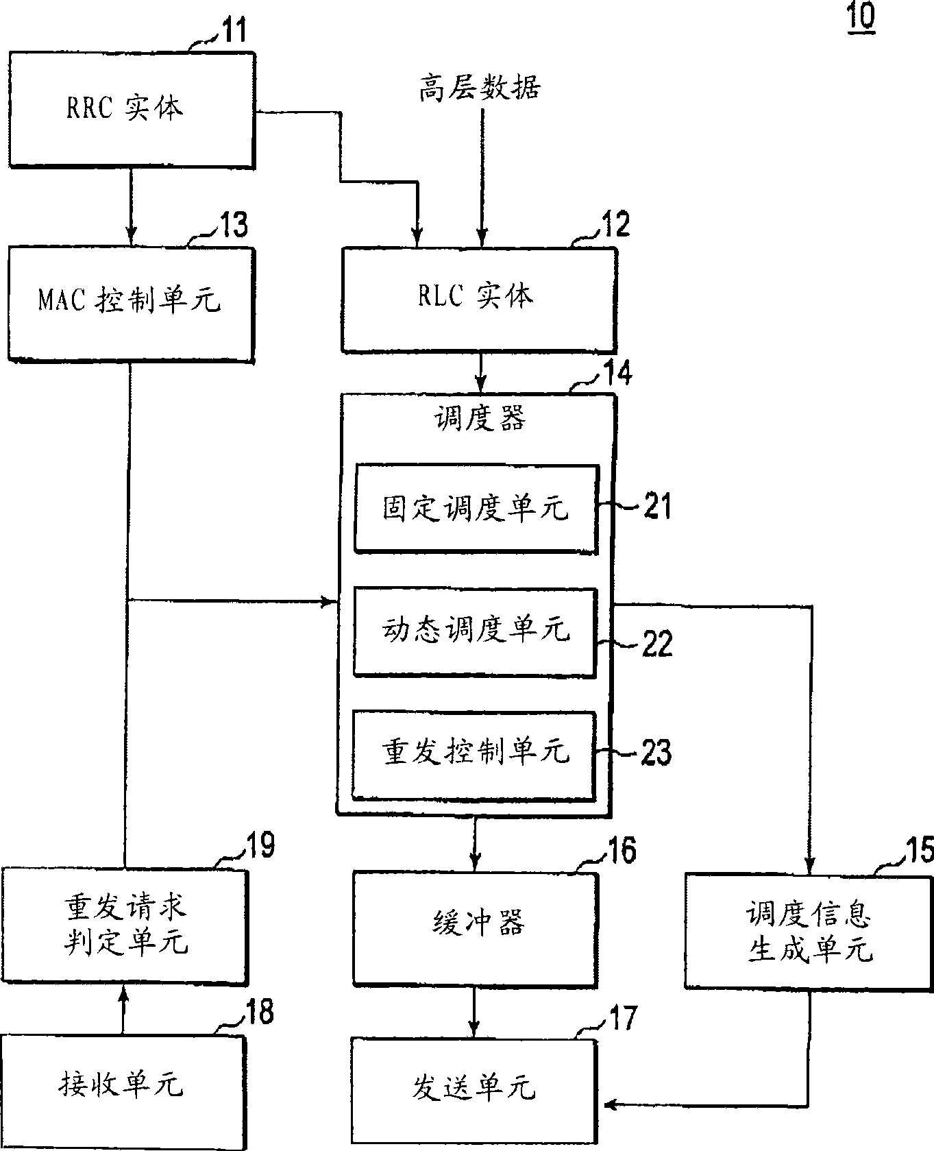
A radio resource allocation method includes: a step in which a radio base station (10) fixedly allocates a radio resource used when transmitting downlink data to a mobile station by persistent scheduling; and a step B in which the radio base station (10) modifies the radio resource to be allocated to the mobile station by dynamic scheduling during a period while the persistence scheduling is applied.

Description

technical field [0001] The present invention broadly relates to radio communication control technology, and particularly relates to a radio resource allocation method and a radio base station when both persistent scheduling (Persistent Scheduling: fixed allocation scheduling) and dynamic scheduling (Dynamic Scheduling: dynamic allocation scheduling) are used together. Background technique [0002] In a conventional communication system such as High Speed ​​Downlink Packet Access (HSDPA: High Speed ​​Downlink Packet Access), a downlink shared control channel (HS-SCCH: High Speed-Shared Control Channel) is used at every predetermined transmission time interval (TTI: Transmission Time Interval), which transmits allocation information on downlink data transmission opportunities to the mobile station. [0003] However, in some services such as voice communication, it is predetermined that downlink data is sent once every tens of ms, so when using a signaling channel (downlink con...

Claims


Application Information

Patent Timeline
Patent Type & Authority Applications(China)
IPC IPC(8): H04W72/12
CPCH04W72/04H04W72/1273H04W72/12H04W72/23
Inventor 原田笃石井美波安部田贞行
Owner NTT DOCOMO INC
Learn More