
A wave piezoelectric power generation device

A piezoelectric power generation and ocean wave technology, which is applied to ocean energy power generation, engine functions, engine components, etc., can solve the problems of poor development of wave energy, low power generation efficiency of devices, and obstacles to large-scale applications, etc., to achieve simple structure, Effect of improving power generation efficiency and avoiding direct contact between machines

Inactive Publication Date: 2019-12-20
SHANGHAI DIANJI UNIV
View PDF8 Cites 0 Cited by
  • Summary
  • Abstract
  • Description
  • Claims
  • Application Information

AI Technical Summary

Problems solved by technology

[0007] At present, there are many types of devices used in wave power generation, but these devices have many disadvantages, such as high initial investment cost, low power generation efficiency, and high mechanical failure rate, which hinder their large-scale application, such as oscillating water column devices. The investment is large, and the conversion efficiency of power generation is only 10%-20%. It cannot develop wave energy well and has no commercial value.
Moreover, the mechanical wear of the wave energy generation device of the traditional piezoelectric generator type is relatively serious, the contact area is small, and the wave energy utilization rate is low

Method used


Image

  • A wave piezoelectric power generation device
  • A wave piezoelectric power generation device

Examples


Embodiment Construction

[0030] The technical content of the present invention is described below through specific specific embodiments, and those skilled in the art can easily understand other advantages and effects of the present invention from the content disclosed in this specification. The present invention can also be implemented or applied through other different specific embodiments, and various modifications and changes can be made to the details in this specification based on different viewpoints and applications without departing from the spirit of the present invention.

[0031] The following is attached figure 1 , 2 The present invention is described in further detail.

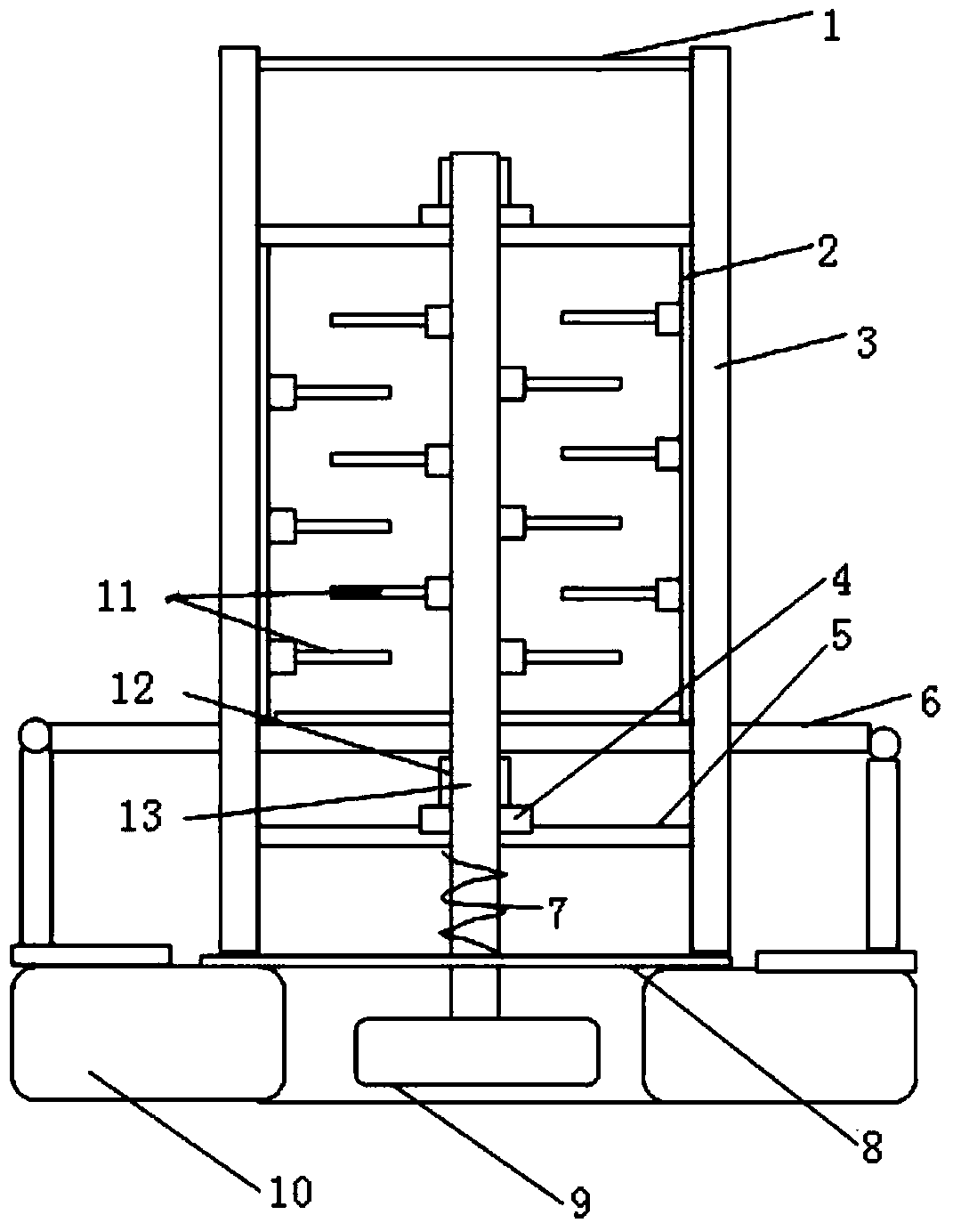
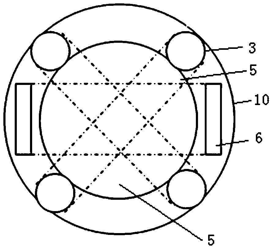
[0032] A wave piezoelectric power generation device, including a floating body and a piezoelectric generator, the floating body includes a supporting floating body 10, a wave energy collection floating body 9, the supporting floating body 10 mainly supports the entire power generation device, and the wave energy collecti...


PUM


Abstract

The invention discloses a novel sea wave piezoelectric electricity generation device which comprises a floating body and a piezoelectric electricity generator. A supporting bottom plate is installed on the outer side of a supporting floating body, a supporting floating body bottom plate is installed on the inner side of the supporting floating body, four guide pillars are installed above the supporting floating body, the piezoelectric electricity generator is installed among the four guide pillars, a top plate is arranged at the top ends of the four guide pillars, and a bearing supporting plate is arranged on the lower portion of the four guide pillars. The piezoelectric electricity generator comprises a surrounding wall arranged among the four guide pillars, piezoelectric vibrators are arranged on the surrounding wall, a transmission shaft is provided with piezoelectric vibrators corresponding to the piezoelectric vibrators on the surrounding wall, permanent magnets are attached to the outer sides of the piezoelectric vibrators, the transmission shaft is connected with a wave energy collecting floating body, a brake device is arranged on a transmission bearing, and an energy storage spring is installed between the bearing supporting plate and the supporting floating body bottom plate. The novel sea wave piezoelectric electricity generation device can effectively prevent the problem of damage to the piezoelectric vibrators of the piezoelectric electricity generation device, and the wave energy utilization rate is increased through the rotary transmission shaft.

Description

technical field [0001] The invention belongs to the technical field of wave power generation, and in particular relates to a wave piezoelectric power generation device. Background technique [0002] The continuous deterioration of the environment in recent years has led more people to think about environmental issues. The main cause of environmental problems is the burning of primary energy. At the same time, the greenhouse effect has also exacerbated the deterioration of the environment. In order to solve these problems, the development of new energy Very fast. [0003] After the Copenhagen Conference in 2015, a new wave of new energy development has emerged again. Compared with solar energy and wind energy, the development of wave energy is far behind. But at present, the development of this renewable energy is in full swing around the world. According to statistics, nearly 40 commercial wave power generation technology companies around the world are engaged in this rese...

Claims


Application Information

Patent Timeline
Patent Type & Authority Patents(China)
IPC IPC(8): F03B13/14
CPCF03B13/14F05B2260/407Y02E10/30
Inventor 王杰谢源谢涛杨鑫肖立健金鹏飞张宏伟
Owner SHANGHAI DIANJI UNIV
Learn More