Plunger piston borehole positioning apparatus

A technology of positioning device and plunger, which is applied in the direction of positioning device, clamping, support, etc., can solve the problems of inability to achieve accuracy and affect the working state of the plunger, and achieve the effect of precise verticality

Inactive Publication Date: 2010-07-21
NINGBO XIANGRUI MACHINERY
View PDF0 Cites 0 Cited by
  • Summary
  • Abstract
  • Description
  • Claims
  • Application Information

AI Technical Summary

Problems solved by technology

However, during the boring process, the perpendicularity between the axis of the through hole 2 on the plunger and the two planes 1 cannot achieve good accuracy, thus affecting the future working state of the plunger

Method used


Image

  • Plunger piston borehole positioning apparatus
  • Plunger piston borehole positioning apparatus
  • Plunger piston borehole positioning apparatus

Examples


Embodiment Construction

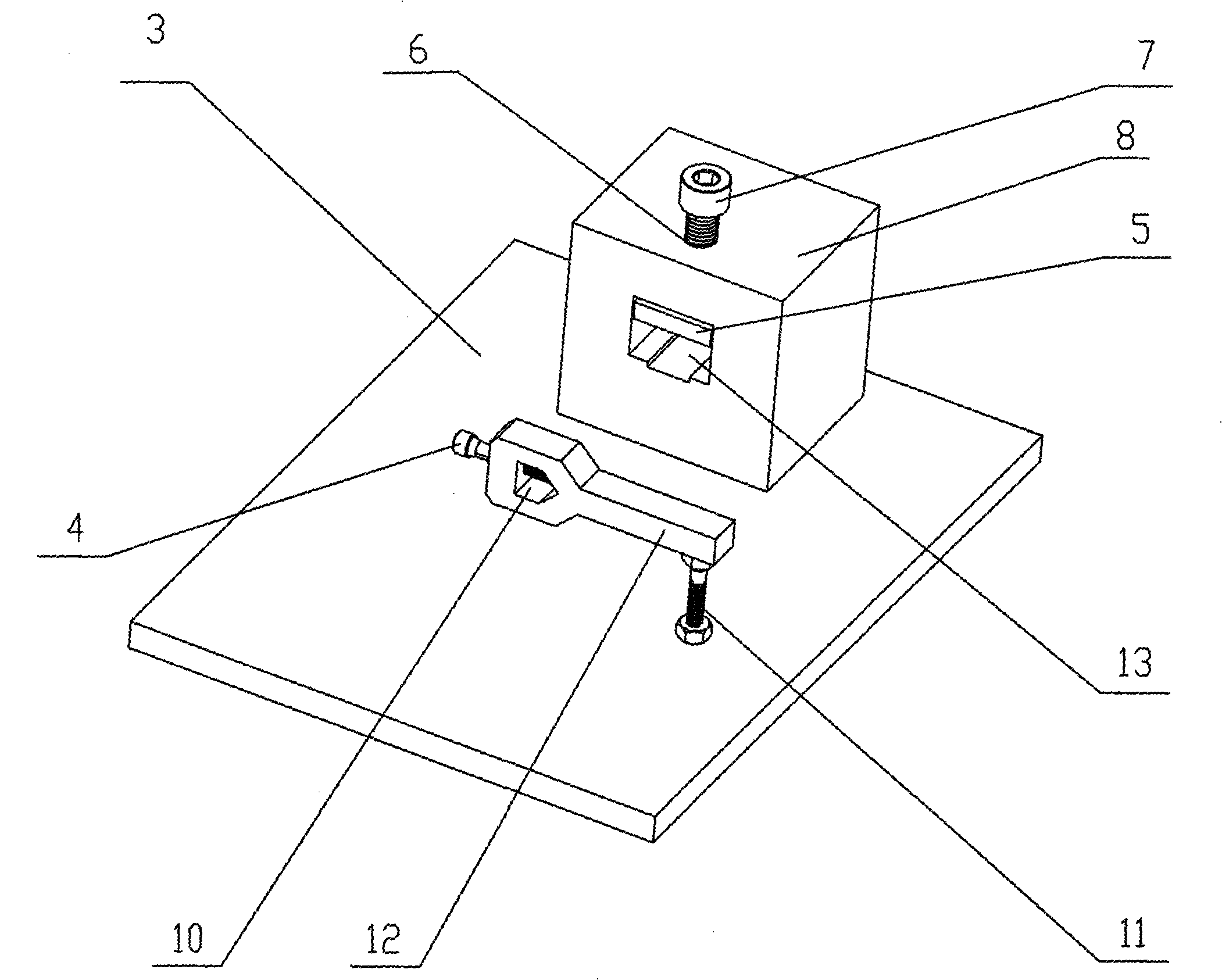
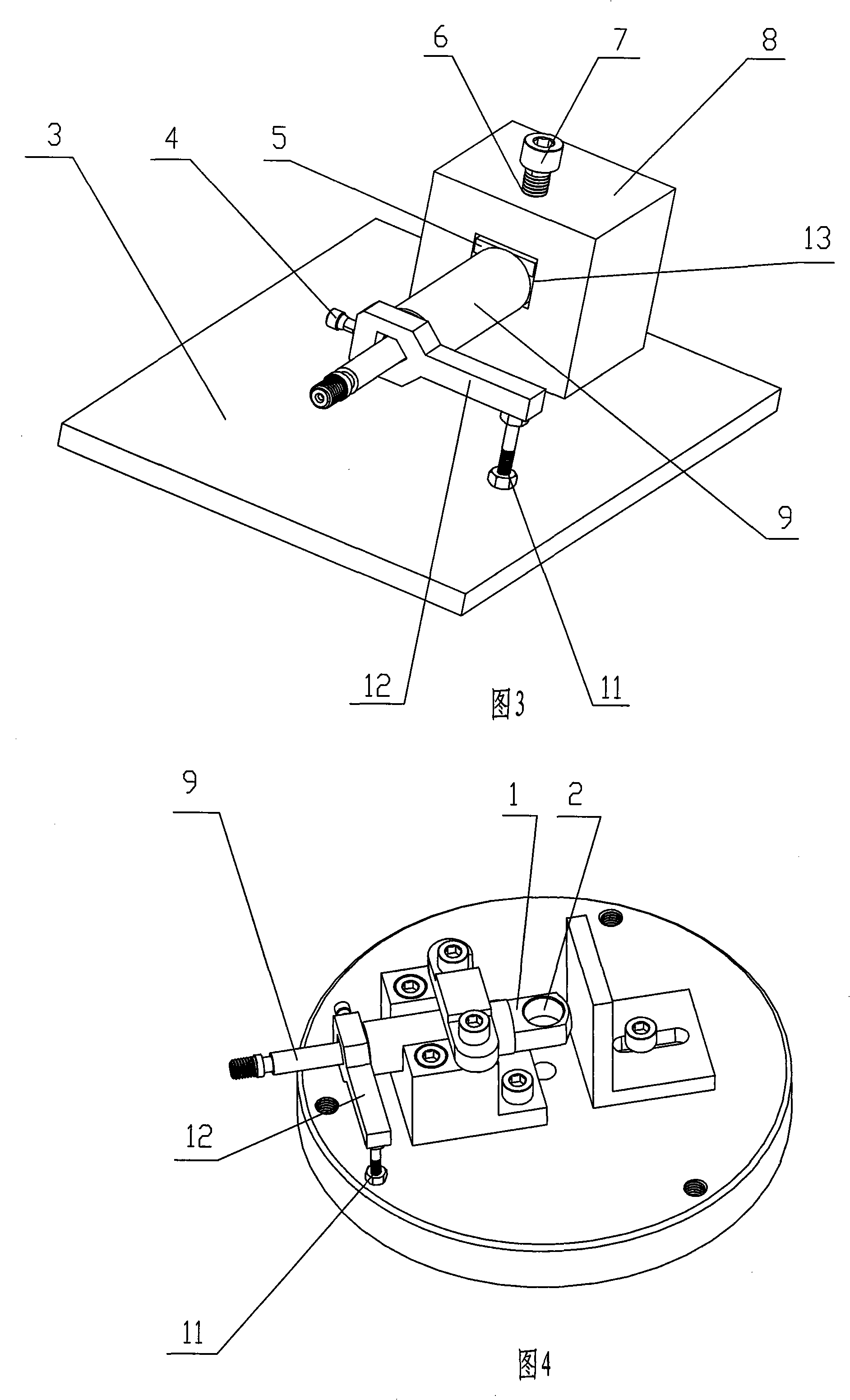
[0011] The present invention will be further described below in conjunction with accompanying drawing and specific embodiment:

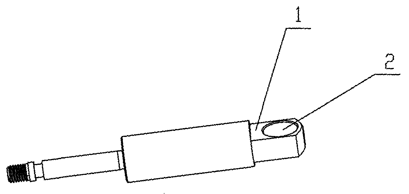
[0012] Such as figure 2 As shown in Fig. 3, in this specific embodiment, the plunger bore positioning device of the present invention includes an angular positioning block 12, a bottom plate 3 and a verticality positioning block 8 connected to the bottom plate 3; on the angular positioning block 12 There is a through hole 10 that allows the plunger rod to pass through; the left end of the angular positioning block 12 is connected with a set screw I4 that can fix the plunger 9 in the through hole 10; the right end of the angular positioning block 12 The bottom is connected with a support screw II11; the base plate 3 is provided with a threaded hole (not shown in the figure), and the bottom of the support screw II11 is screwed in the threaded hole to realize a detachable connection with the base plate 3; the vertical Degree positioning block 8 is pro...


PUM


Abstract

The present invention discloses a plunger piston boring positioning device which comprises an angular positioning block (12) installed with a through hole (10) and a verticality positioning block (8) connected with the base board (3). The left end of angular positioning block (12) is connected with a positioning screw I(4). The base of right end of angular positioning block (12) is connected witha supporting screw II(2) which is detachably connected with the base board (3). One side of verticality positioning block (8) relatively to the angle positioning block (12) is installed with a concave hole (13) which is used for placing the boring end of plunger piston (9) and has a base surface and a top surface that are equally horizontal surfaces. A cushion block (5) which has a base surface parallel with the base surface and top surface of concave hole (13) is provided in the concave hole (13). The top part of verticality positioning block (8) is provided with a threaded hole (6) communicated with the concave hole (13). A screw III(7) is connected with the threaded hole (6). The base part of screw III(7) is connected with the cushion block (5). The plunger piston boring positioning device of the invention can guarantee the accurate verticality between the boring axis of processed plunger piston and the top surface and the bottom surface of boring.

Description

Technical field: [0001] The invention relates to a plunger boring positioning device. Background technique: [0002] There is a plunger in the prior art, such as figure 1 As shown, one end of the plunger is provided with two vertically symmetrical planes 1 , and a through hole 2 perpendicular to the two planes 1 is connected between the two planes 1 . At present, in the machining process, in order to ensure the positional accuracy and surface roughness of the above-mentioned through hole 2, workers generally adopt a boring process, that is, rough or fine boring the above-mentioned through hole 2, so that the through hole 2 can be To achieve the required machining accuracy. However, during the boring process, the perpendicularity between the axis of the through hole 2 on the plunger and the two planes 1 cannot achieve good accuracy, thereby affecting the subsequent working state of the plunger. Invention content: [0003] The technical problem to be solved by the present...

Claims


Application Information

Patent Timeline
Patent Type & Authority Patents(China)
IPC IPC(8): B23Q3/18B23Q3/06
Inventor 李德祥
Owner NINGBO XIANGRUI MACHINERY
Why Eureka
Try Eureka