Eureka AIR delivers breakthrough ideas for toughest innovation challenges, trusted by R&D personnel around the world.

Single-side engagement rolling point scanning measurement method and apparatus for non-circular gear error

A non-circular gear, single-sided meshing technology, used in measuring devices, machine gear/transmission mechanism testing, using optical devices, etc. Diagnosis, geometric accuracy difficulties, etc., to achieve the effect of complete and comprehensive accuracy measurement and evaluation

Inactive Publication Date: 2009-07-08
BEIJING UNIV OF TECH
View PDF0 Cites 8 Cited by
  • Summary
  • Abstract
  • Description
  • Claims
  • Application Information

AI Technical Summary

Problems solved by technology

[0007] Since the pitch curve of non-circular gears is non-circular, the theoretical profile shape (including tooth profile, tooth direction and pitch) of each tooth on non-circular gears will be different relative to the position of the pitch curve. Therefore, for It is very difficult and time-consuming to measure the contour shape of each tooth of a non-circular gear tooth by tooth to obtain the individual geometric accuracy of non-circular gears; the measurement of the comprehensive transmission error of non-circular gears can only obtain non-circular gears or The comprehensive error of the non-circular gear pair, but the single geometric error of the non-circular gear cannot be obtained, so it is difficult to correctly evaluate and analyze the quality of a single non-circular gear, and it is also difficult to diagnose the processing system of the non-circular gear

Method used


Image

  • Single-side engagement rolling point scanning measurement method and apparatus for non-circular gear error
  • Single-side engagement rolling point scanning measurement method and apparatus for non-circular gear error
  • Single-side engagement rolling point scanning measurement method and apparatus for non-circular gear error

Examples


Embodiment Construction

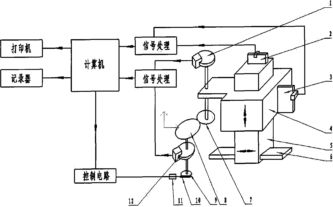
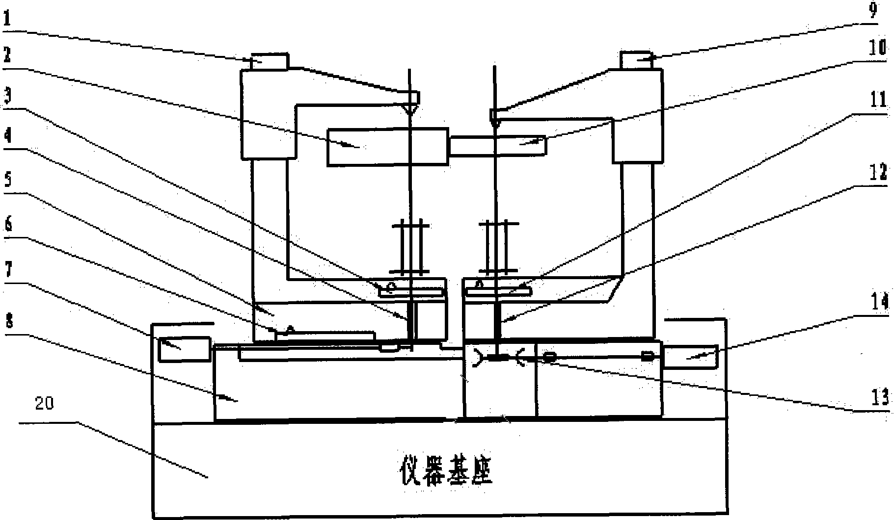
[0034] Attached below figure 2 , 3 , 4 further illustrate the present invention:

[0035] figure 2 , image 3 and Figure 4 Middle: 1 is the main shaft part of the non-circular gear to be tested, 2 is the non-circular gear to be tested, 3 is the angle encoder, 4 is the shaft system of the gear to be tested, 5 is the radial measuring slide, 6 is the long grating, and 7 is the servo motor , 8 is a working base, 9 is a measuring element shafting part, 10 is a measuring element, 11 is an angle encoder, 12 is a rotary spindle, 13 is a transmission mechanism, 14 is a servo motor, and 20 is an instrument base;

[0036] Figure 5 Among them, 200 is the tooth ridgeline, and 201 is the tooth profile ridgeline;

[0037] Figure 6 Among them, 60 multi-head worm measuring elements, 61 is the second angle encoder, 62 is the second measured non-circular gear, and 63 is the second angle encoder;

[0038] Figure 7 Among them, 71 is a long grating, 72 is a third angle encoder, 200 i...


PUM


Abstract

The invention relates to a method and a device for measuring the scanning of one-sided mesh rolling point of error of a noncircular gear. A measured noncircular gear is arranged on a shaft system of a measured gear; the shaft is coaxially provided with an angle coder; a measuring element is arranged on a rotary mainshaft; the rotary mainshaft is coaxially provided with an angle coder; the rotary mainshaft is arranged on a fixed bed body and is driven by a mainshaft servo motor; a mainshaft part of the measured noncircular gear is arranged on a radial measuring slide board; the radial measuring slide board is driven by a servo motor of the radial measuring slide board to realize the precise radial motion of pitch curve according to the radius vector of the change of the pitch curve of a noncircular gear theory; and strict designed transmission relation is kept between rotations of the mainshaft servo motor and the servo motor of the radial measuring slide board so as to realize the one-sided mesh transmission between the measured noncircular gear and the measuring element. Under the condition of once mounting, the method and the device complete the mensuration of single geometrical deviation, integrated tangential deviation and whole error of the noncircular gear.

Description

technical field [0001] The invention relates to a non-circular gear error measurement technology and device, and belongs to the technical fields of precision testing technology, instrument and mechanical transmission. Background technique [0002] Non-circular gears can be considered as a variant of cylindrical gears, and their rolling pitch circles are non-circular, called pitch curves. When a pair of non-circular gears whose center distance remains constant meshes, the transmission ratio changes. Therefore, non-circular gears can be used to achieve variable speed ratio transmission. Similar to cylindrical gears, non-circular gear errors can be divided into two categories: single geometric errors and comprehensive transmission errors. The single geometric error of non-circular gears includes tooth profile deviation, tooth direction (helix) deviation and tooth pitch deviation of non-circular gears; the comprehensive transmission error of non-circular gears includes tangent...

Claims


Application Information

Patent Timeline
IPC IPC(8): G01M13/02G01B21/00G01B11/00
Inventor 石照耀张斌谢华锟
Owner BEIJING UNIV OF TECH
Why Eureka
Eureka Blog
Learn More