
Method and device for measuring errors of face gear by scanning single-face meshed rolling points

A technology of single-face meshing and measuring devices, which is applied in the direction of measuring devices, machine gear/transmission mechanism testing, optical devices, etc., can solve difficult gear processing system diagnosis and analysis, difficult full-scan measurement, and obtain comprehensive transmission of face gears Accuracy and other issues

Inactive Publication Date: 2010-06-02
BEIJING UNIV OF TECH
View PDF0 Cites 7 Cited by
  • Summary
  • Abstract
  • Description
  • Claims
  • Application Information

AI Technical Summary

Problems solved by technology

[0008] Since the theoretical contour shape of face gear teeth is different at different positions (such as different radii or tooth heights), for face gears, in order to evaluate its accuracy and quality in use, the traditional coordinate measurement method is used to measure the profile of a single tooth It is very difficult to measure the full tooth width "point-to-point" or full-scan measurement of the geometric parameter coordinates; furthermore, if the profile shape of each tooth of the face gear is to be measured tooth by tooth to obtain the individual geometric accuracy of the face gear It is more difficult and troublesome; at the same time, it is difficult to obtain the comprehensive transmission accuracy of the face gear from the single geometric error of the face gear, so it is difficult to evaluate the comprehensive transmission quality of the face gear
[0009] As for the measurement of the comprehensive transmission error of the face gear, although the tangential comprehensive deviation of the gear can be obtained by the single-sided meshing tester, or the radial comprehensive deviation of the gear can be obtained by the double-sided meshing tester, but the surface can not be obtained from the corresponding measurement. The single geometric error of the gear makes it difficult to analyze the error of the face gear, and it is also difficult to diagnose and analyze the gear processing system

Method used


Image

  • Method and device for measuring errors of face gear by scanning single-face meshed rolling points
  • Method and device for measuring errors of face gear by scanning single-face meshed rolling points
  • Method and device for measuring errors of face gear by scanning single-face meshed rolling points

Examples


Embodiment 1

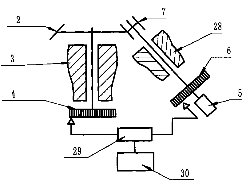
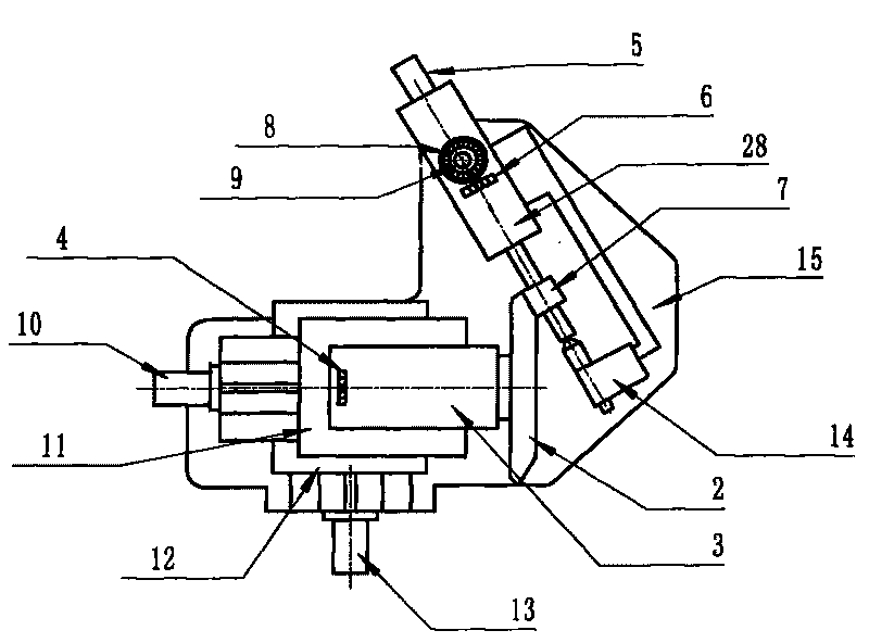
[0047] Embodiment 1 adopts such as image 3 In the horizontal structure shown, the measuring element mounting shaft system 28 and the face gear mounting shaft system 3 are installed horizontally. The measured surface gear 2 is accurately installed on the measured gear precision shaft system 3, and a high-precision circular grating 4 is coaxially installed on the shaft. Measuring element 7 (with tooth profile / or tooth direction measuring ridge) is accurately installed on measuring element rotating main shaft system 28 and supported by support tailstock 14, and high-precision circular grating 6 is coaxially installed on shafting system 28 . The position adjustment of the measured surface gear 2 and the measuring element 7: the measured surface gear shaft system component 3 is installed on the axial carriage 11 with a high-precision long grating, and the carriage is driven by a motor 10 . The axial carriage is fixed on the radial adjustment carriage 12 at the same time, and the ...

Embodiment 2

[0049] Embodiment 2 adopts such as Figure 4 In the vertical structure shown, the face gear installation shaft system 3 is installed in the vertical direction, and the measuring element installation shaft 28 is installed obliquely. Similarly, the face gear 2 and the measuring element 7 are installed on the precision shaft system 3, and circular gratings are coaxially installed on each shaft system. The position adjustment of the measured surface gear 2 and the measuring element 7: the measured surface gear shaft system component 3 is installed on the radial adjustment carriage 12 with a high-precision long grating, and the carriage moves in the radial direction through the rotation handle 19 , the position of the carriage is determined according to the theoretical position of the face gear transmission; in addition, the relative height of the measuring element 7 and the face gear 2 can be adjusted through the height adjustment handle 16, the height adjustment carriage 17 also ...

Embodiment 3

[0051] Embodiment 3 adopts such as Figure 5 In the variant vertical structure shown, the face gear installation shaft system 3 is installed obliquely in the vertical plane, and the measuring element installation shaft system 28 is installed horizontally. The difference between it and the vertical mechanism is that the gear shaft system part 3 of the measured surface can swing in the vertical plane, and the angle adjustment between the measured surface gear 2 and the measuring element 7 is adjusted by the angle adjustment mechanism 21 . The acquisition and processing of the signal are the same as in Embodiment 1.


PUM


Abstract

The invention relates to a technology and a device for measuring errors of a face gear by scanning single-face meshed rolling points, belonging to the field of the technology and the device for precision measuring and metering. A spaced-tooth measuring element with a special measuring crest line is combined with the face gear to the measured to form single-face meshing drive; round grating signals which are installed coaxially with the spaced-tooth measuring element and the face gear to the measured are collected; and the signal geometric error and the integrated drive error of the face gear to be measured are obtained through processing the round grating signals by a computer. In the invention, the signal geometric error and the integrated drive error of the face gear to be measured are measured rapidly and accurately in the process of clamping the face gear for one time, and the integrated motion precision of the drive pair of the face gear can be measured rapidly and accurately.

Description

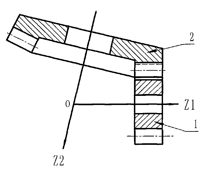
technical field [0001] The invention relates to a method and a device for scanning and measuring a face gear error of a single meshing rolling point, and belongs to the field of precision test and measurement technology and instruments. Background technique [0002] The so-called face gear drive (Face Gear Drive) is a gear drive in which a cylindrical gear and a bevel gear mesh. figure 1 It is a schematic diagram of face gear transmission, in which gear 1 is an ordinary cylindrical gear (pinion), and gear 2 is a face gear (bevel gear). The bevel gear is processed by the generation method with a tool of the same size as gear 1. According to the relationship between the two axes of the pinion and the face gear, the face gear transmission can be divided into several types such as orthogonal and non-orthogonal, offset and non-offset. In general, face gear transmission has the following advantages: [0003] 1) The pinion is an involute cylindrical gear, and its axial position e...

Claims


Application Information

Patent Timeline
Patent Type & Authority Applications(China)
IPC IPC(8): G01M13/02G01B11/00
Inventor 石照耀林虎林家春谢华锟
Owner BEIJING UNIV OF TECH
Learn More