Gear assembly for driving an electrical switching contact

A transmission device and electric switch technology, applied in electric switches, contact drive mechanisms, contact operation mechanisms, etc., can solve the problems of variation in contact timing, inaccurate transmission characteristics, and troublesome trimming of chute devices. achieve the effect of fast conversion

Inactive Publication Date: 2009-07-08
SIEMENS AG
View PDF1 Cites 1 Cited by
  • Summary
  • Abstract
  • Description
  • Claims
  • Application Information

AI Technical Summary

Problems solved by technology

In addition, the gearing suffers from wear after many movement processes
This can lead to inaccuracies in the transmission characteristics an

Method used


Image

  • Gear assembly for driving an electrical switching contact
  • Gear assembly for driving an electrical switching contact
  • Gear assembly for driving an electrical switching contact

Examples


Embodiment Construction

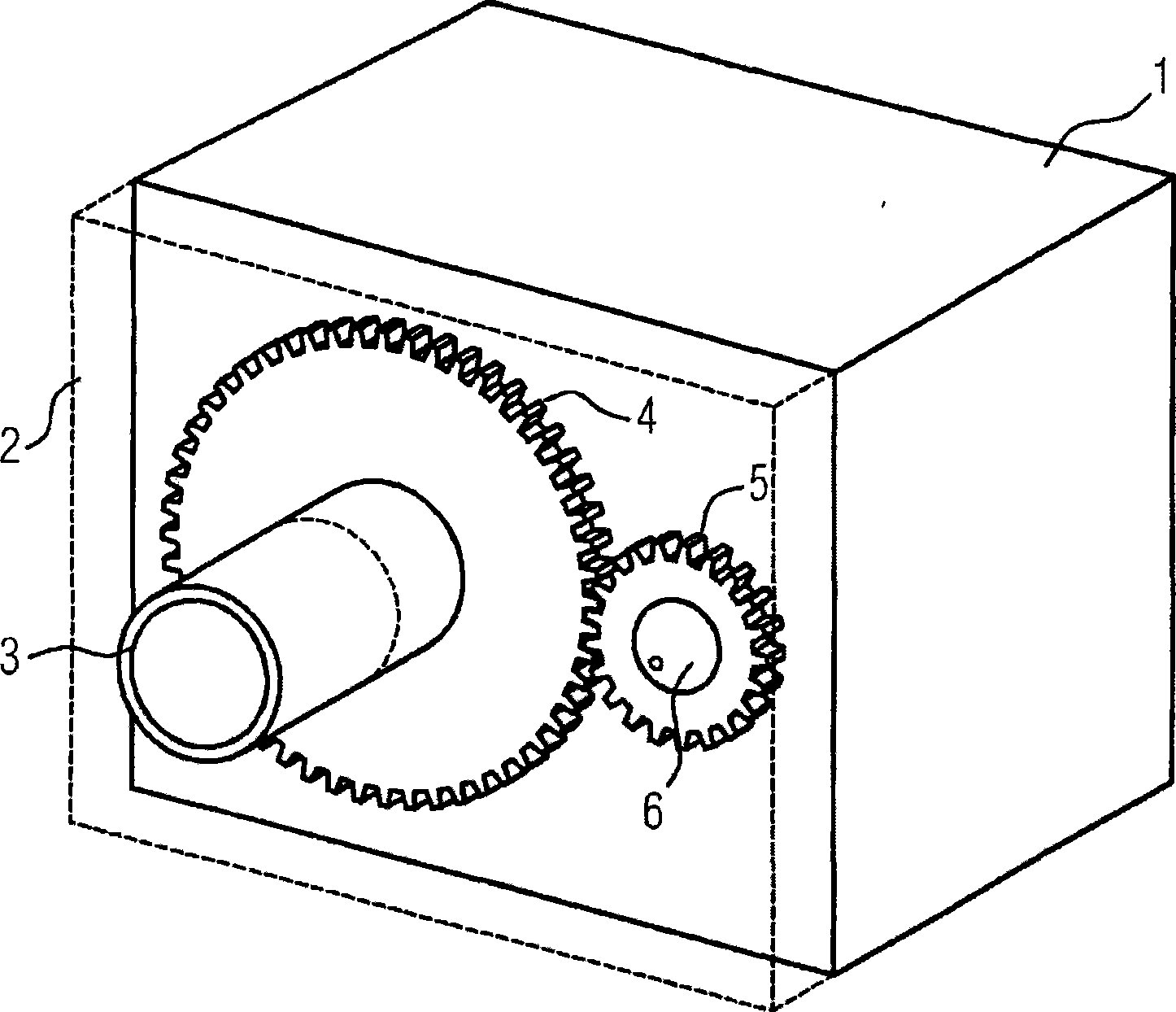
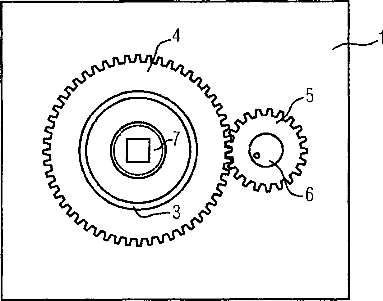
[0040] The transmission device is located inside the frame 1 . The frame basically has a cuboid-shaped structure, and the transmission is installed inside it. To see it more clearly, in figure 1 Middle panel 2 is indicated by a dotted line. A drive shaft 3 protrudes from the panel 2 . The drive shaft 3 is of tubular design and is mounted on the machine frame 1 so as to be rotatable about the longitudinal axis of the tube. The drive shaft gear 4 surrounds the drive shaft 3 concentrically. The drive shaft gear 4 meshes with the drive pinion 5 . The drive pinion 5 is mounted on the drive pinion shaft 6 . Drive shaft gear 4 and drive pinion 5 are covered by panel 2 . In order to interface with the primary distribution equipment, the drive shaft 3 can be directly or indirectly connected to the shaft for driving the primary switch contacts. This is achieved, for example, by the tubular drive shaft 3 being fitted onto the shaft in a positively closed manner.

[0041] figure...


PUM


Abstract

Disclosed is a gear assembly comprising a gate sampling element (11) which cooperates with a gate passage (10) of a gate arrangement (9). The gate arrangement (9) is provided with a first partial element (20a) and a second partial element (20b), each of which delimits the gate passage (10) in some sections.

Description

technical field [0001] The invention relates to a transmission device for driving at least one electrical switch contact, comprising a sliding slot device with a sliding slot connected to the sliding slot probe part and movable relative to the sliding slot probe part. Background technique [0002] A transmission of this type is known, for example, from German patent DE 10 205 334 C1. There, the first and the second switching contact are each connected via the gate probe piece to the gate of the gate arrangement. By moving the slide unit, a movement of the switching contacts can be caused. Due to the configuration of the link, one of the two switching contacts moves while the other remains stationary. The chute device is designed as a whole, wherein the chute is determined by the shape of the chute device. [0003] After many switching operations, wear phenomena develop on the switching contacts. These are, for example, burning phenomena based on switching arcs formed at ...

Claims


Application Information

Patent Timeline
IPC IPC(8): H01H3/42
CPCH01H2003/323H01H3/42H01H9/0066
Inventor 勒内·冈瑟塞巴斯蒂安·戈谢尔彼得·米勒夫斯基
Owner SIEMENS AG
Why Eureka
Try Eureka