

Prosthesis for enterostomy patients
a technology for enterostomy and prosthesis, which is applied in the field of prosthesis for enterostomy patients, can solve the problems of complex and frequent maintenance, lack of voluntary continence control, and jeopardizing the quality of life of patients
Active Publication Date: 2021-06-15
BENCINI CLAUDIO
View PDF5 Cites 0 Cited by
- Summary
- Abstract
- Description
- Claims
- Application Information
AI Technical Summary
Benefits of technology
[0038]The main aim of the present invention is to devise a prosthesis for enterostomy patients adaptable to the positions taken by the patient without causing discomfort and inconvenience, allowing for maximum freedom of movement and increasing, compared to the devices of known type, comfort and convenience of use.
[0039]Another object of the present invention is to devise a prosthesis for enterostomy patients which greatly increases the quality of life of enterostomy patients. Another object of the present invention is to devise a prosthesis for enterostomy patients which allows to control the outflow of the intestinal contents thus allowing patients to use commonly widespread toilets, including the toilets in the means of transport without the need to dispose of collection bags full of intestinal contents with their own means.
[0040]A further object of the present invention is to devise a prosthesis for enterostomy patients which eliminates the inconvenience linked to the need to perform periodic cleaning procedures of the intestinal contents by means of the complex and costly practice of irrigation.
[0041]Another object of the present invention is to devise a prosthesis which allows overcoming the mentioned drawbacks of the prior art within the ambit of a simple, rational, easy, effective to use and affordable solution.
Problems solved by technology
As a result of the amputation of the terminal stretch of the bowels, voluntary continence control is lacking, necessitating the discharge to the outside of the intestinal contents.
These bags, however, have several drawbacks that hinder the patient's normal social reintegration, seriously jeopardizing the patient's quality of life.
In fact, in addition to creating aesthetic problems, the use of such bags, not providing for the recovery of voluntary evacuation control, involves a complex and frequent maintenance, to be repeated at short time intervals and also several times a day, forcing the patient to stay close to toilets.
Furthermore, the use of such bags is not free from possible complications related to the presence of bonding agents which enable it to adhere to the patient's skin.
Added to this is the fact that these bags require frequent changes, resulting in a high expenditure of time in the change of the used bags and difficulties in the disposal of the same by the patient.
Nevertheless, the implantation of the above artificial prostheses requires for complex surgery having many possible complications such as infections of the peristomal tissue, as well as the need for periodical irrigation intended to keep the bowels cleaned over time.
Even this second type of artificial prosthesis has however some drawbacks related to the presence of adhesive substances which, as a result of prolonged contact with the skin, often cause irritation.
Added to this is the need to provide for frequent irrigations of the bowels, so that the latter remains empty; it is easy to understand that the aforementioned types of prostheses are not very appealing to patients, greatly increasing the discomfort linked to a clinical condition already complex in itself.
Besides these types of prostheses there are others that provide for the bonding of the ring to the skin and the association by interlocking to the closure element; also in this case, however, repeated and frequent irrigations of the bowels are necessary, increasing the discomfort on the part of patients involved in these situations.
Such prostheses however, being made of a rigid material, are rather annoying during the flexion movements of the torso, or for example with a prolonged time in the sitting position.
It is easy to understand how the use of such prosthesis of known type proves complex and cumbersome, to which the fact is added that it requires a complex kit of integrated parts.
Method used
View moreImage
Smart ImageViewing Examples

Examples
first embodiment
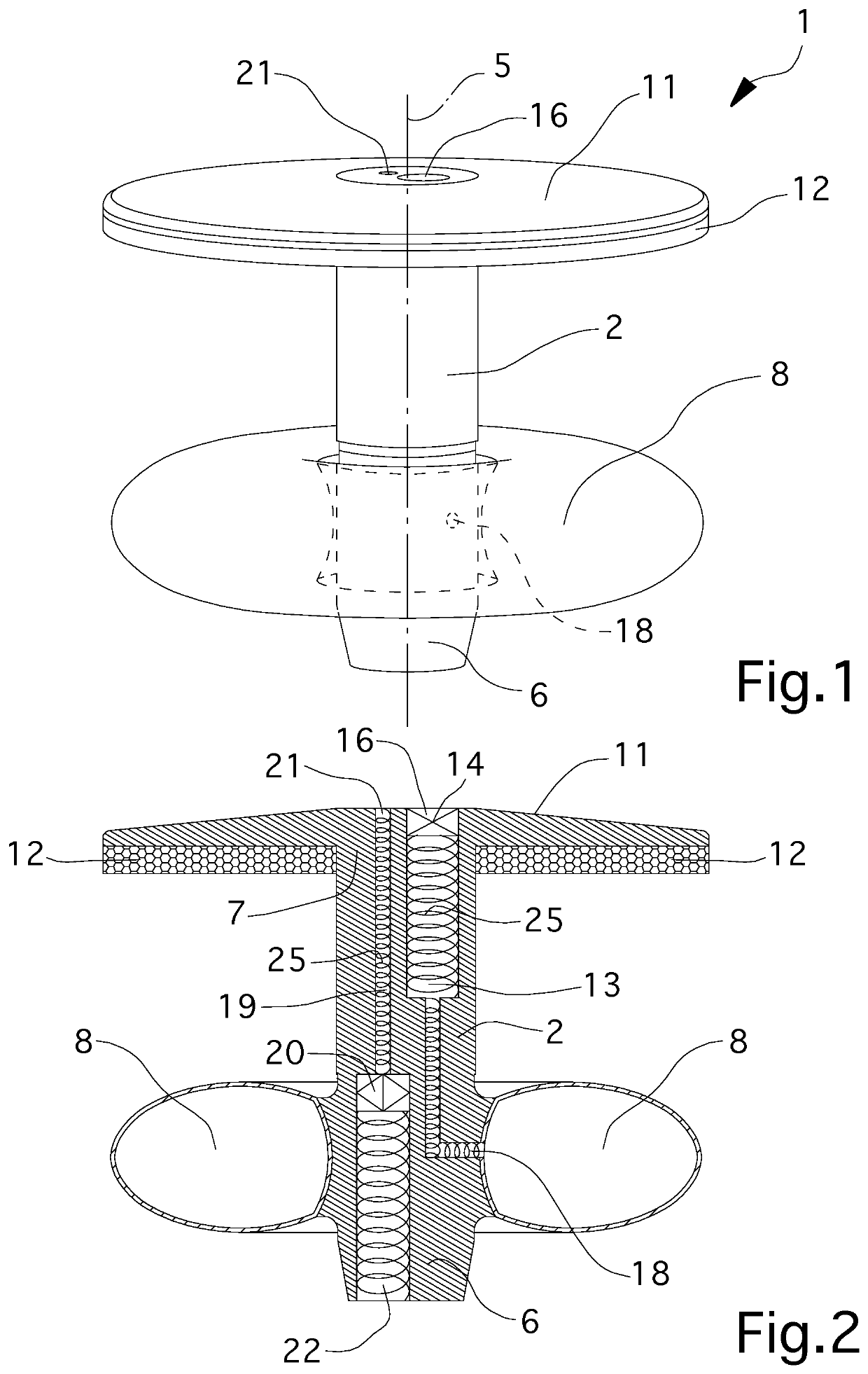
[0044]FIG. 1 is a front view of the prosthesis according to the invention in a first embodiment;
[0045]FIG. 2 is a sectional view of the prosthesis of FIG. 1;
second embodiment
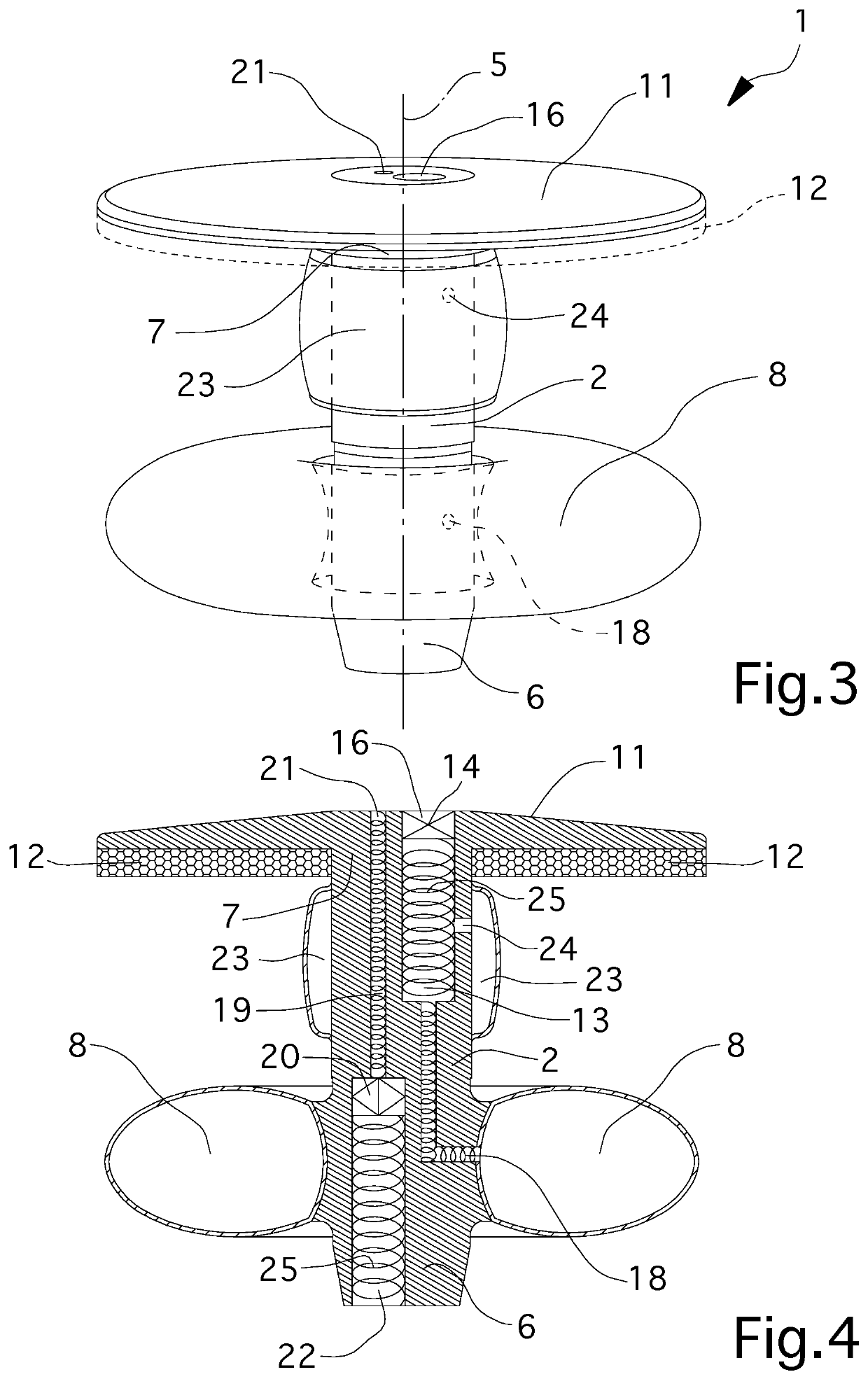
[0046]FIG. 3 is a front view of the prosthesis according to the invention in a second embodiment;
[0047]FIG. 4 is a sectional view of the prosthesis of FIG. 3;
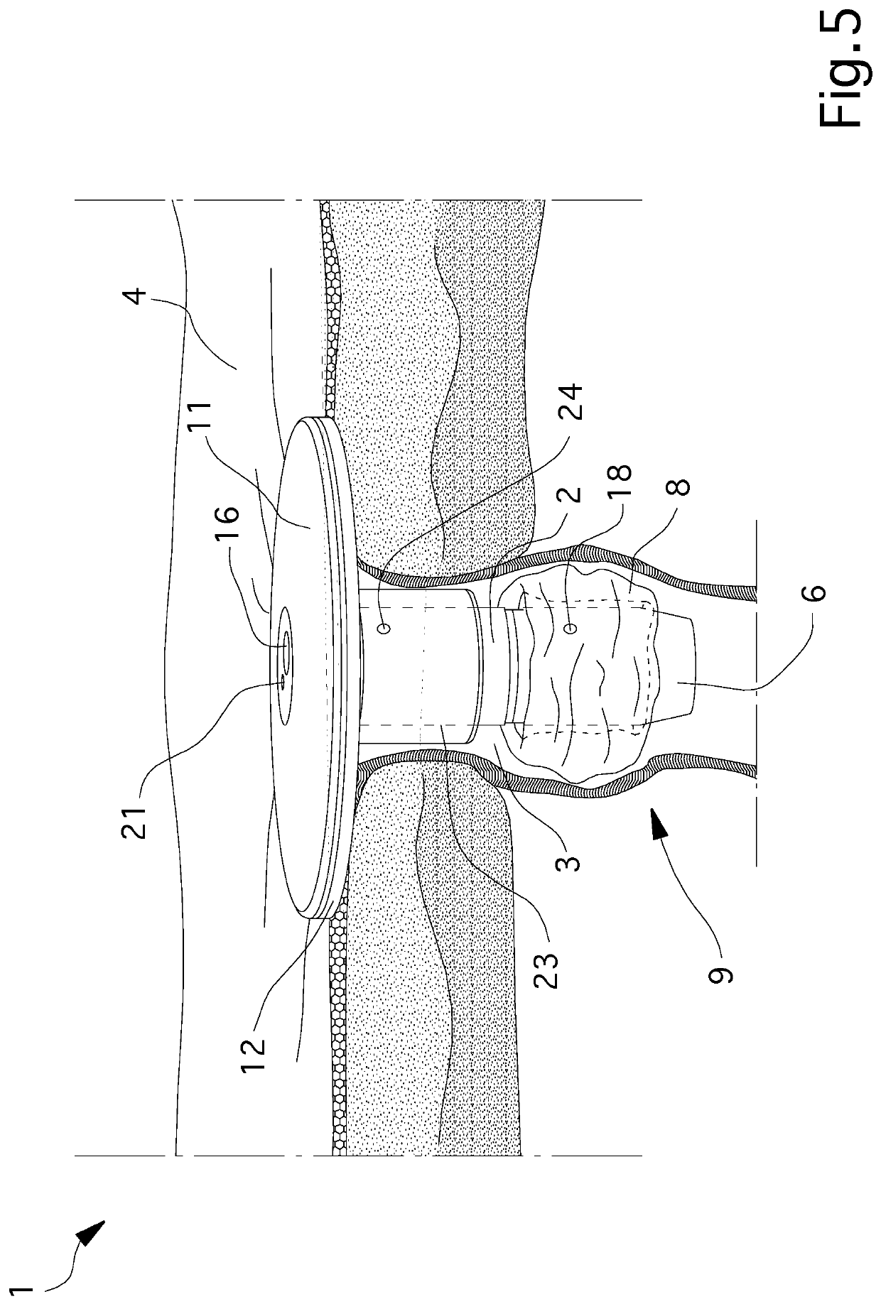
[0048]FIG. 5 is a schematic representation of the prosthesis of FIG. 3 in a first operating mode;
[0049]FIG. 6 is a schematic representation of the prosthesis of FIG. 3 in a second operating mode.
Login to View More PUM
 Abstract
The prosthesis for enterostomy patients comprises: a tubular element of elongated shape and insertable substantially to size inside of a stoma made on the abdominal wall of a patient; a first obstruction means to obstruct at least one area of the stoma, associated with a first end of the tubular element and movable between a restricted configuration and an enlarged configuration to allow the insertion / extraction into / from the stoma respectively, and to prevent leakage of feces from the stoma itself; a first through duct made on the tubular element, communicating with the first obstruction balloon and having valve connectable to a forced introduction / extraction disposable syringe for conduction of a fluid into / from the first obstruction balloon; a second through duct made on the tubular element, communicating with the inside of the stoma and having an active carbon filter for the outflow of gases from the stoma itself; and an external retaining element associated with a second end of the tubular element opposite to the first end and able to cooperate with at least one portion of the abdominal wall and having at least two through holes arranged at the first duct and the second duct; in which at least one of the tubular element and the retaining element is made at least partially of a flexible material.
Description
RELATED APPLICATIONS[0001]This application is the U.S. National Phase of and claims priority to International Patent Application No. PCT / 162016 / 057122, International Filing Date Nov. 25, 2016, entitled Prosthesis For Enterostomy Patients; which claims benefit of Italian Application No. UB2015A005928 filed Nov. 26, 2015 entitled Protesi Per Enterostomizzati; both of which are incorporated herein by reference in their entireties.TECHNICAL FIELD[0002]The present invention relates to a prosthesis for enterostomy patients.BACKGROUND ART[0003]In medical practice, as a result of severe intestinal diseases or to complete surgery, amputation of the terminal stretch of the bowels may result necessary, which must be put into connection with the outside in order to be able to discharge the contents thereof.[0004]For this purpose it is common practice to make an enterostomy, i.e. a practice intended to constitute a “stoma”, i.e. a praeternatural opening made in the abdominal wall and intended to...
Claims
Login to View More Application Information
Patent Timeline
 Patent Type & AuthorityPatents(United States)
IPC IPC(8): A61F5/441A61F5/44A61F5/445A61F5/00
CPCA61F5/4407A61F5/0093A61F5/441A61F5/445A61F5/4405A61F2005/4455
InventorBENCINI, CLAUDIO
OwnerBENCINI CLAUDIO