
Movable radiation protection screen

a radiation protection screen and movable technology, applied in the field of ionizing radiation protection equipment, can solve the problems of limiting the operator's ability to move, rapid fatigue, and not allowing the operator to work under optimal conditions, and achieves the effect of protecting the operator efficiently and large freedom of movemen

Active Publication Date: 2021-06-29
LEMER PROTECTION ANTI X PAR ABREVIATION SOC LEMER PAX
View PDF13 Cites 2 Cited by
  • Summary
  • Abstract
  • Description
  • Claims
  • Application Information

AI Technical Summary

Benefits of technology

The patent describes a screen that can be placed in front of an examination table to protect the operator from X-rays while still having full freedom of movement. The screen can be moved by the operator to the side or above the patient depending on the procedure to be performed. This design allows for efficient protection and enables the operator to move the screen without moving the entire screen in case of contact with other apparatus.

Problems solved by technology

. . , but which do not always cover the entire body, and whose important weight is detrimental to the operator's comfort, limits his ability to move and entails a rapid fatigue.
However, those different structures do not allow an operator to work under optimal conditions.
Especially, certain ones of them are not well adapted for allowing an operator situated on the protected side of the screen to get with his arms or his hands to the other side of that screen, for example in order to intervene on a part of the patient's body that is exposed to the radiation.
Further, the structures of screens known up to now, often reveal as being inconvenient for moving the appliances of the operating room, especially the fluoroscopic appliances.

Method used


Image

  • Movable radiation protection screen
  • Movable radiation protection screen
  • Movable radiation protection screen

Examples


Embodiment Construction

[0042]The following description with reference to the enclosed drawings which are enclosed as not limiting examples, will make understand well what the invention consists of and how it can be carried out.

[0043]On the enclosed drawings

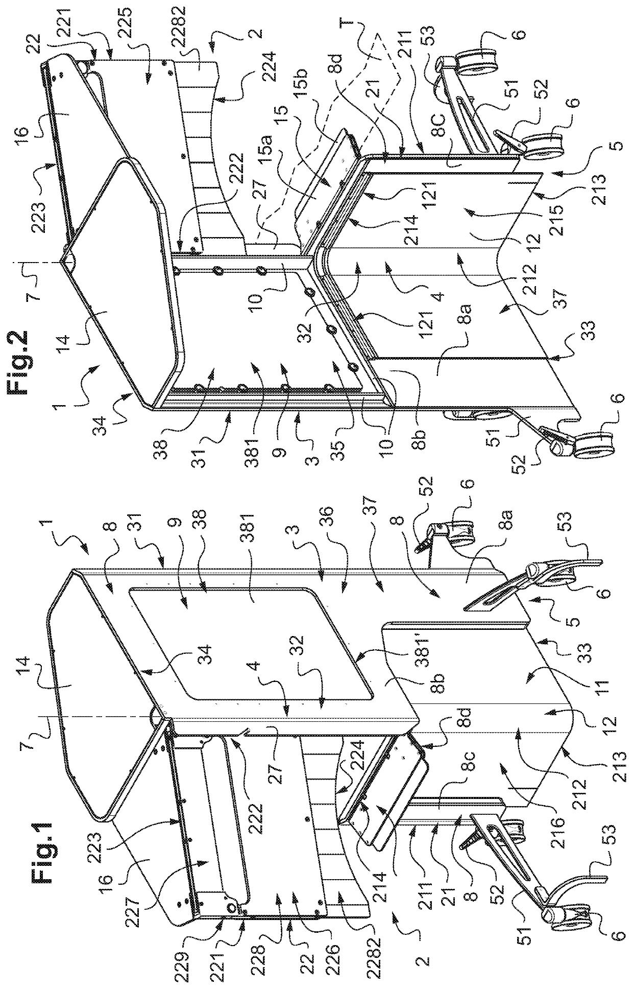
[0044]FIG. 1 shows a radioprotective screen according to the invention as a perspective view from the outer face (opposite to the positioning space of the operator, the upper part of the front wall structure being angularly offset with respect to the lower part of said front wall structure;

[0045]FIG. 2 shows the radioprotective screen of FIG. 1 as a perspective view from the inner face, i.e. from the side of the positioning space of the operator;

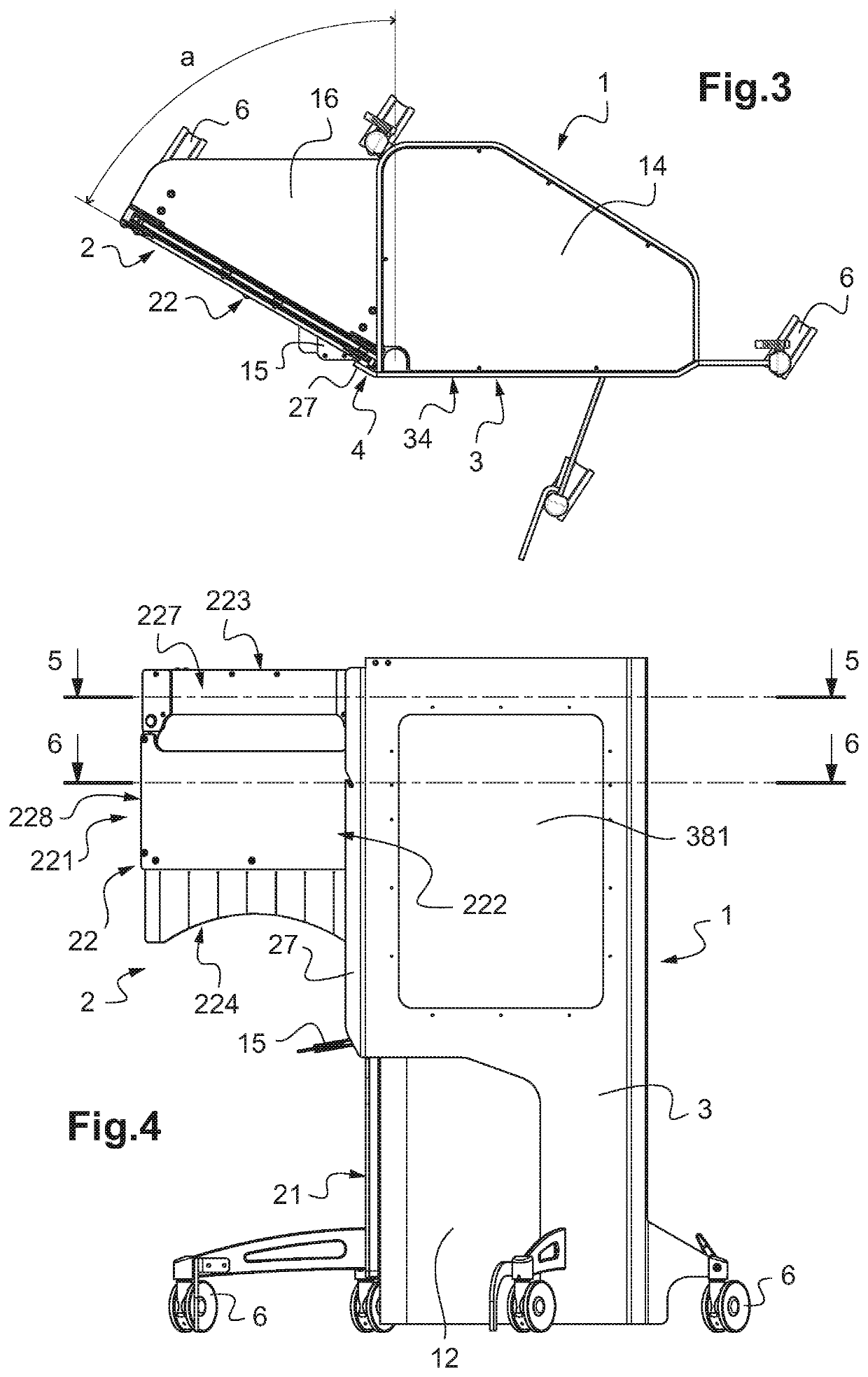
[0046]FIG. 3 is a view from above the radioprotective screen represented on FIGS. 1 and 2;

[0047]FIG. 4 is a side view of the radioprotective screen represented on FIGS. 1-3;

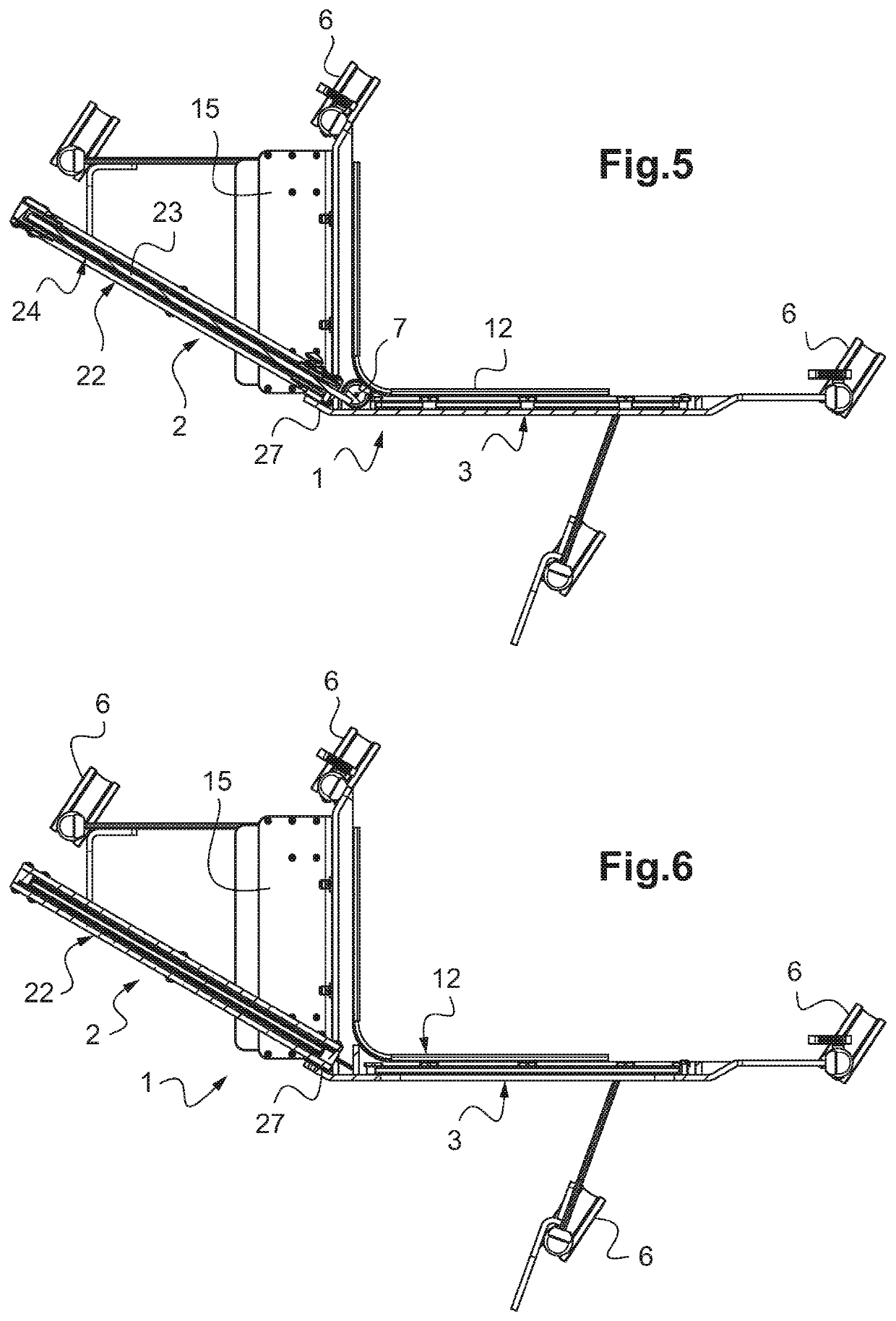
[0048]FIG. 5 is a sectional view of the radioprotective screen according to plane 5-5 of FIG. 4;

[0049]FIG. 6 is a sectional view of the radi...


PUM


Abstract

Disclosed is a radiation protection screen for protecting an operator from ionizing radiation, which screen includes a front partition structure that is made of one or more radiation protection materials and a side partition structure that is made of one or more radiation protection materials, the partitions being joined together at a vertical or substantially vertical corner border, and which screen includes feet that are equipped with wheels that rest on the ground. Furthermore, according to the invention, this screen is arranged such that the front partition structure includes a lower portion and an upper portion that may be moved with respect to each other, the upper portion of the front partition structure being mounted so as to be able to pivot in the region of the corner border, about a vertical or substantially vertical pivoting axis.

Description

TECHNICAL FIELD THAT THE INVENTION IS RELATED TO[0001]The present invention is generally related to the field of equipment for protection from ionizing radiation.[0002]It is especially related to radioprotective screens which are used in the medical field or other fields for protecting an operator from the emission of ionizing radiation such as X-rays. It is also related to a cover-shaped equipment for wrapping such screens by covering them for the purpose of using them in a sterile protected environment.TECHNICAL BACKGROUND[0003]During certain examinations or interventions, the patients are exposed to ionizing radiation, especially of the X-rays type, which are used for checking, for diagnostic or for treatment.[0004]That is particularly the case for interventions such as catheterization, installing pacemakers, vascular, neurological or urological examinations, CIM (Cardiac Rhythm Management), CRT (Cardiac Resynchronization Therapy) or during application of fluoroscopy techniques.[...

Claims


Application Information

Patent Timeline
Patent Type & Authority Patents(United States)
IPC IPC(8): A61B6/10G21F3/00
CPCA61B6/107G21F3/00G21F7/02G21F5/14G21F5/06E05Y2900/51E05D15/1007E05Y2201/638E05F15/657A61B6/10
Inventor LEMER, PIERRE-MARIE
Owner LEMER PROTECTION ANTI X PAR ABREVIATION SOC LEMER PAX
Learn More