Method for controlling the operation of a reversible belt retractor in a motor vehicle

a technology of reversible belts and retractors, which is applied in the direction of process control, pedestrian/occupant safety arrangement, instruments, etc., can solve the problems of not being able to unwind the tensioned belt strap, the restraint belt cannot be unwound from the belt reel, and the freedom of movement of the occupant is highly restricted, so as to improve the safety, reliability and comfort of the restraint belt system. , the effect of high probability

Active Publication Date: 2009-10-06
DAIMLER AG
View PDF19 Cites 0 Cited by
  • Summary
  • Abstract
  • Description
  • Claims
  • Application Information

AI Technical Summary

Benefits of technology

[0002]Conventional restraint belt systems in motor vehicles comprise a winding-up mechanism for automatically winding up the loose belt strap around a belt reel. The effect achieved by the automatic winding-up is that the belt, when put on, rests loosely and comfortably on an occupant's body and, when the seat belt is not in use, is rolled up around the belt reel (comfort-providing state). When the belt has been put on, the unwinding of the belt in the comfort-providing state is easily possible in order to provide the occupant with substantial freedom of movement. In this case, a small torque counter to the unwinding direction is produced by a retracting spring.
[0004]Some restraint belt systems also have a belt retractor, the operation of which can be controlled in order, in the case of an accident, to shorten the loose belt strap and / or to pull an occupant toward the back rest of the seat into a position associated with a reduced risk of injury.
[0009]A method for controlling the operation of a belt retractor with a blocking device is described in international publication WO 02 / 46005. The belt retractor here acts, inter alia, as a release device for releasing a belt extraction lock. This belt extraction lock acts on a belt reel in such a manner that, in the blocking state of the belt extraction lock, a belt strap wound up on the belt reel is prevented from unwinding, and only in the comfort-providing state is the unwinding of the belt strap possible. The belt extraction lock can only change from the blocking state into the comfort-providing state when the vehicle-sensitive acceleration sensor does not detect any acceleration above an acceleration threshold value. After the belt extraction lock comes into effect, the operation of the belt retractor is controlled by a release signal at a release time in order to bring about the change of the belt extraction lock from the blocking state into the comfort-providing state.
[0011]It is the object of the invention to improve the safety, the reliability and the comfort of a restraint belt system with a reversible belt retractor. This object is achieved by the features claimed.
[0013]An advantage of the achievement according to the invention of the object mentioned is that reliable information about the actual state of the acceleration sensor is used in a simple manner by means of the algorithm based on a model of the acceleration signal to determine the release time. By means of this reliable information about the actual state of the acceleration sensor, the release time can be defined in such a manner that, with specifiable, high probability, the acceleration sensor does not cause the belt extraction lock to be brought into effect, i.e. that, with specifiably high probability, following the control of the operation of the reversible belt retractor at the release time, the belt strap is released for unwinding.

Problems solved by technology

If the belt extraction lock is effective, then it is no longer possible to unwind the tensioned belt strap, and the freedom of movement of an occupant is highly restricted.
The belt system comprises a belt extraction lock which can be activated by an acceleration sensor and, in the activated state, has the effect of it not being possible for the restraint belt to be unwound from a belt reel.
However, this second belt extraction lock is not suitable, in the case of an accident, for absorbing the forces acting on the belt strap and for restraining the belt.

Method used


Image

  • Method for controlling the operation of a reversible belt retractor in a motor vehicle
  • Method for controlling the operation of a reversible belt retractor in a motor vehicle

Examples


Embodiment Construction

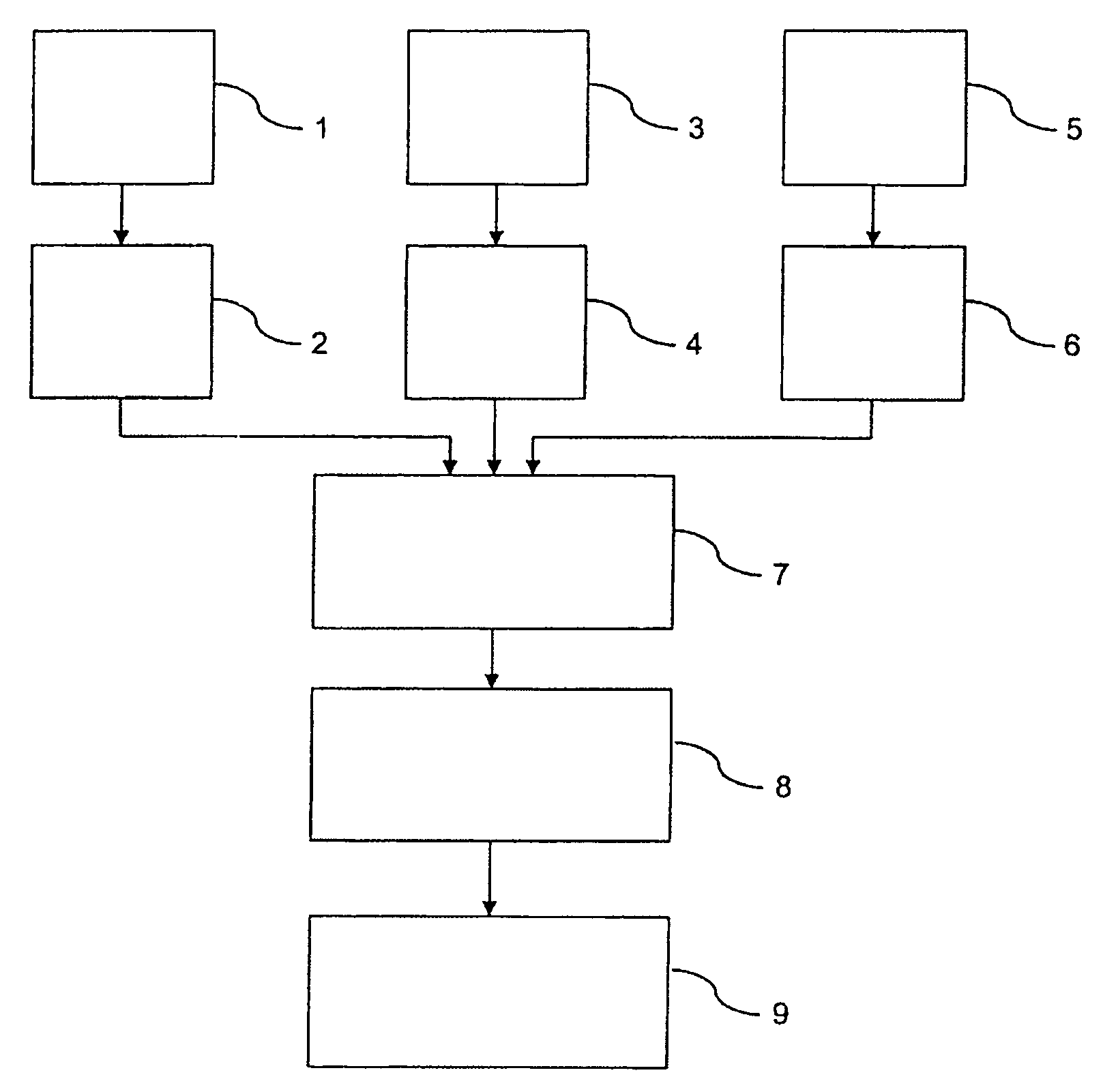
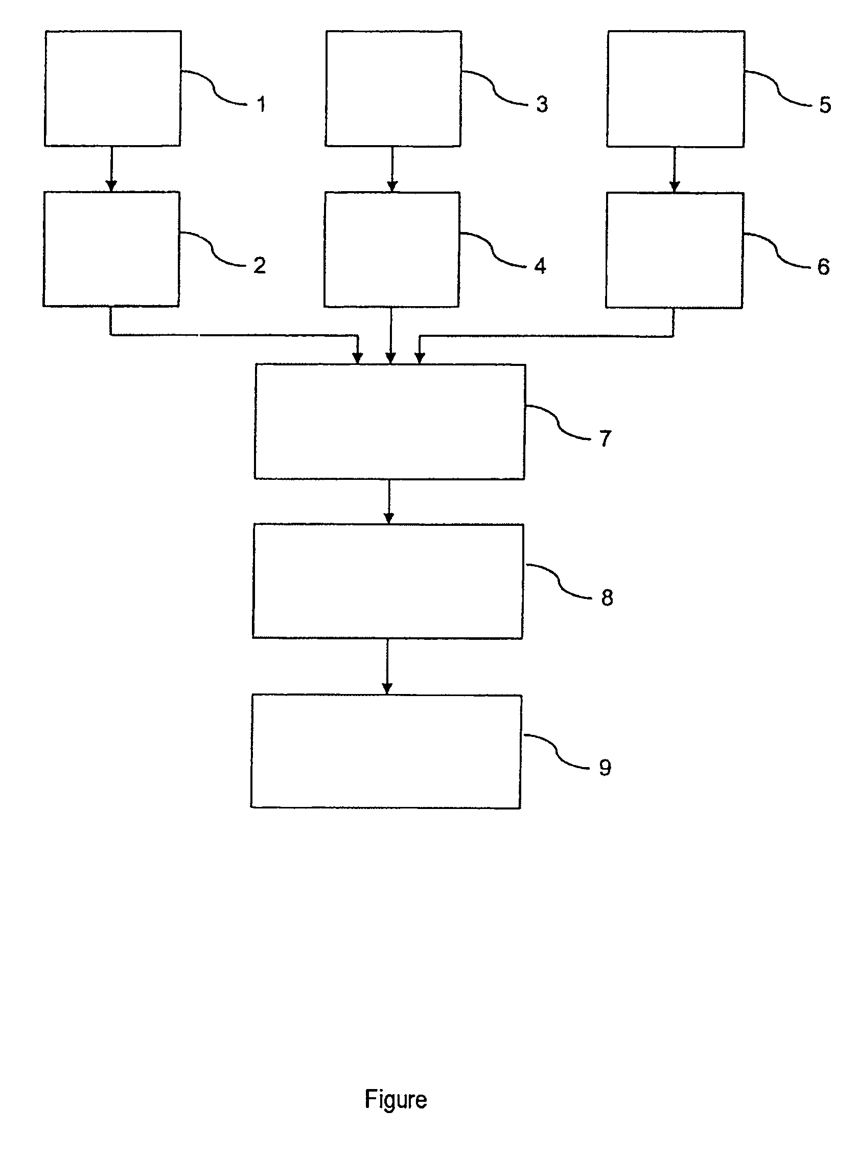
[0022]In step 1, a wheel speed, or preferably a plurality of wheel speeds, is / are detected and, from the detected wheel speeds, the longitudinal acceleration of the vehicle is determined. As an alternative, the longitudinal acceleration may also be determined in another manner or may be directly detected by means of a sensor. The longitudinal acceleration determined is made available for further processing in step 2. It is inquired in step 2 whether the longitudinal acceleration is below a specifiable acceleration threshold value.

[0023]In step 3, the rotational acceleration of the vehicle about its own vertical axis is detected by sensor or is determined by means of auxiliary variables, and is made available for further processing in step 4. In step 4, it may additionally be inquired whether the yaw velocity, the yaw acceleration or an auxiliary variable taking these two variables into consideration is below a specifiable threshold value.

[0024]In step 5, the transverse acceleration ...


PUM


Abstract

In a method for controlling the operation of a reversible belt retractor to release a belt extraction lock of a restraint belt in a motor vehicle, the lock can be activated by an acceleration sensor. After the belt retractor has been triggered as a consequence of a hazardous situation having been detected and after the hazardous situation has been recognized as being over, the operation of the belt retractor is controlled by a release signal at a release time in order to bring about the release of the belt extraction lock to shift it from a blocking state into a comfort-providing state. The release time is determined by a sensor model algorithm based on a model of the acceleration sensor from at least one variable characterizing the running dynamics.

Description

BACKGROUND AND SUMMARY OF THE INVENTION[0001]This invention relates to a method for controlling the operation of a reversible belt retractor to release a belt extraction lock of a restraint belt in a motor vehicle.[0002]Conventional restraint belt systems in motor vehicles comprise a winding-up mechanism for automatically winding up the loose belt strap around a belt reel. The effect achieved by the automatic winding-up is that the belt, when put on, rests loosely and comfortably on an occupant's body and, when the seat belt is not in use, is rolled up around the belt reel (comfort-providing state). When the belt has been put on, the unwinding of the belt in the comfort-providing state is easily possible in order to provide the occupant with substantial freedom of movement. In this case, a small torque counter to the unwinding direction is produced by a retracting spring.[0003]In particular so that a belt system of this type can restrain an occupant in the event of a collision, ther...

Claims


Application Information

Patent Timeline
Patent Type & Authority Patents(United States)
IPC IPC(8): B60R21/00B60R21/01B60R21/0132B60R21/015B60R22/34B60R22/46
CPCB60R21/0132B60R22/321B60R22/3416B60R22/322B60R21/0155B60R2021/01327B60R2022/4666B60R2022/469B60R2021/01272
Inventor BOGENRIEDER, RALFEBERLE, WALTERJUSTEN, RAINERROEHM, HANSVILLINO, GUIDOWAGNER, ALFREDWOLDRICH, MARKUS
Owner DAIMLER AG
Why Eureka
Try Eureka