Developing device, toner particle carrying roller, image forming apparatus, image forming system, and method of manufacturing toner particle carrying roller

A technology for developing devices and image bearing bodies, applied in the fields of electric recording technology using charge patterns, equipment for electric recording technology using charge patterns, and electric recording techniques, which can solve the problem of different concave sizes, depths, shapes, and arrangement methods Uniformity, dispersion, image fog, etc.

Inactive Publication Date: 2009-07-15
SEIKO EPSON CORP
View PDF3 Cites 2 Cited by
  • Summary
  • Abstract
  • Description
  • Claims
  • Application Information

AI Technical Summary

Problems solved by technology

[0005] In this developing device, when the unevenness of the surface of the toner particle carrying roller is formed by sandblasting, the size, depth, shape, and arrangement method of the concave portions are not uniform
Therefore, for example, toner particles entering deep recesses cannot be charged well because they are not rolled.
In this way, due to the non-uniform unevenness of the unevenness on the surface of the toner particle carrying roller, there is a possibility that the charge failure of the toner particles locally occurs, or the toner particles enter small recesses to cause filming.
In addition, if the toner particles are not well charged, there is a problem that the toner particles leak from the developing device and disperse into the image forming device, or generate fog on the image, etc.

Method used


Image

  • Developing device, toner particle carrying roller, image forming apparatus, image forming system, and method of manufacturing toner particle carrying roller
  • Developing device, toner particle carrying roller, image forming apparatus, image forming system, and method of manufacturing toner particle carrying roller
  • Developing device, toner particle carrying roller, image forming apparatus, image forming system, and method of manufacturing toner particle carrying roller

Examples


no. 2 approach to no. 4 approach

[0166] [Other Embodiments (Second Embodiment to Fourth Embodiment, etc.)]

[0167] The developing device and the like according to the present invention have been described above based on the above-mentioned embodiments, but the above-mentioned embodiments of the invention are only for making the present invention easier to understand, and are not intended to limit the present invention. The present invention can be changed and improved without departing from the gist thereof, and of course equivalents thereof are also included in the present invention.

[0168] In the above-mentioned embodiments, an image forming apparatus has been described taking a full-color laser printer as an example, but the present invention can also be applied to various image forming apparatuses such as monochrome laser printers, copiers, and facsimile machines.

[0169] In addition, in the above-mentioned embodiment, the example in which the printer has a plurality of attaching and detachable parts ...

no. 2 approach

[0173] >

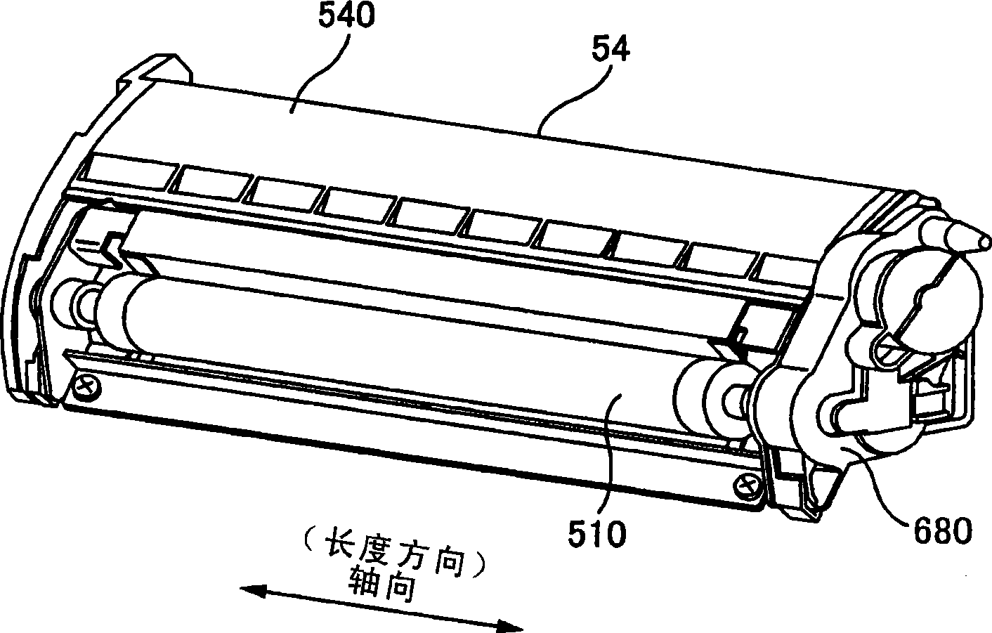
[0174] Here, use Figure 15 to Figure 18 A structural example of the developing roller 510 of the developing device according to the second embodiment will be described. Figure 15 It is a schematic perspective view of the developing roller 510, showing the spiral first groove 1518a and the second groove 1518b whose winding directions are different from each other. Figure 16 It is a schematic front view of the developing roller 510 , showing the positional relationship of the uneven processed portion 1512 , the non-embossed processed portion 1514 , and the intermediate portion 1516 of the developing roller 510 . Figure 17 is a schematic diagram of the cross-sectional shape of the trench 1518 . Figure 18 yes Figure 16 A-A cross-sectional schematic diagram, showing the difference between the depth of the groove 1518 of the concave-convex processing part 1512 and the depth of the groove 1518 of the middle part 1516. exist Figure 15 to Figure 18 In , in order ...

no. 3 approach

[0203] >

[0204] Here, use Figure 19 to Figure 22 A structural example of the developing roller 510 of the developing device according to the third embodiment will be described. Figure 19 It is a schematic perspective view of the developing roller 510, showing the helical first groove 2518a and the second groove 2518b whose winding directions are different from each other. Figure 20 It is a schematic front view of the developing roller 510 , showing the positional relationship between the groove forming portion 2512 and the non-groove forming portion 2514 of the developing roller 510 . Figure 21 is a schematic diagram of the cross-sectional shape of the trench 2518. Figure 22 yes Figure 20 The A-A cross-sectional schematic diagram shows the difference between the depth of the groove 2518 in the central portion 2512a and the depth of the groove 2518 in the two end portions 2512b. In addition, in Figure 19 to Figure 22 In , in order to make the figure easier to unde...


PUM


Abstract

A developing device includes a container that contains toner particles that are for developing a latent image borne by an image bearing body, and a toner-particle bearing roller that has a helical groove portion on a surface thereof that is for bearing the toner particles, the helical groove portion having an inclination with respect to an axial direction and a circumferential direction of the toner-particle bearing roller and being formed having a uniform pitch in the axial direction.

Description

[0001] This application is a divisional application based on the invention patent application filed on October 31, 2006 with the application number 200610150467.X and the title of the invention "developing device and image forming device". technical field [0002] The present invention relates to a developing device and an image forming device. Background technique [0003] A developing device that performs development using toner particles is known as a developing device having a toner particle carrying roller for carrying toner particles accommodated in a toner particle container and performing development. . [0004] In order to limit the layer thickness of the toner particles carried by the toner particle carrying roller and to charge the toner particles, such a developing device is provided with a layer thickness that is in contact with the toner particle carrying roller that carries the toner particles. Limit parts. In addition, the surface of the toner particle carr...

Claims


Application Information

Patent Timeline
Patent Type & Authority Applications(China)
IPC IPC(8): G03G15/08G03G15/01
Inventor 山田阳一有贺友洋樱井升功刀正尚冈本克巳加藤洋
Owner SEIKO EPSON CORP
Why Eureka
Try Eureka