Control method, apparatus and system for concrete pump vehicle

The technology of a concrete pump truck and a control method, which is applied in the control field, can solve problems such as energy waste, and achieve the effect of avoiding waste and realizing energy-saving control.

The technology of a concrete pump truck and a control method, which is applied in the control field, can solve problems such as energy waste, and achieve the effect of avoiding waste and realizing energy-saving control.

CN101487343AInactive Publication Date: 2009-07-22SANY HEAVY IND CO LTD (CN)

Image

  • Control method, apparatus and system for concrete pump vehicle
  • Control method, apparatus and system for concrete pump vehicle
  • Control method, apparatus and system for concrete pump vehicle

Examples


Embodiment 2

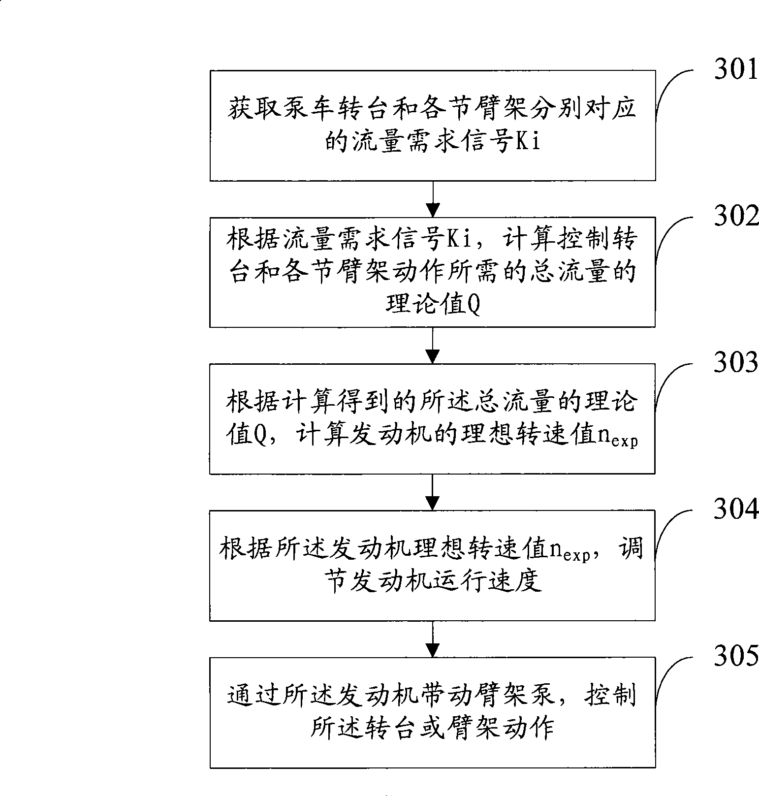
[0139] In the second embodiment, the push of the control handle corresponding to the turntable and each section of the jib is used as the flow demand signal as an example to describe in detail.

[0140] Assume that the flow rate required to control the movement of the turntable and each section of the jib is Qi (i=0, 1, 2, 3, 4). Then according to formula (1), we can get:

[0141] Qi=|Ki|×ARMi_Max_Flux (5)

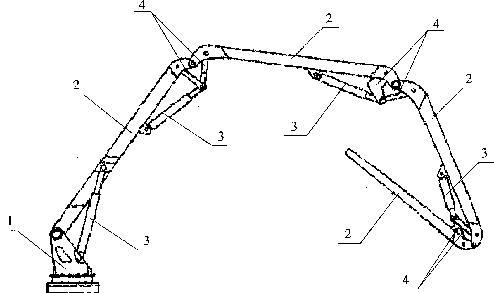
[0142] by figure 1 Take the four-boom pump truck as an example:

[0143] The flow value required to control the movement of the turntable is: Q0=|K0|×ARM0_Max_Flux.

[0144] The flow value required to control the movement of 1# boom is: Q1=|K1|×ARM1_Max_Flux.

[0145] Step 407: Calculate the current value Ii required to control the action of the proportional valve corresponding to the turntable and each boom according to the flow value Qi required to control the movement of the turntable and each boom.

[0146] According to the flow control curve of the proportional v...


PUM


Abstract

The invention provides a control method of a concrete pump truck. The control method comprises the following steps: flow demand signals corresponding to a rotating floor and each arm support respectively are obtained; a theoretical value of total flow needed for controlling the movements of the rotating floor and each arm frame is calculated according to the flow demand signals; an ideal value of rotating speed of an engine is calculated according to the theoretical value of the total flow obtained by calculation; the operating speed of the engine is adjusted according to the ideal value of the rotating speed obtained by calculation; and an arm support pump is driven by the engine to control the movements of the rotating floor and each arm support. The invention further provides control equipment and a system of the concrete pump truck. By using the control method, the equipment and the system, the energy-saving control of the arm supports of the pump truck can be realized.

Description

technical field [0001] The invention relates to the field of control, in particular to a control method, device and system for a concrete pump truck. Background technique [0002] The concrete pump truck is a device that integrates the pumping mechanism for pumping concrete and the arm system for distributing materials on the chassis of the car. The pumping mechanism uses the power provided by the chassis engine to pressurize the concrete in the hopper into the pipeline attached to the boom. The operator controls the movement of the boom to send the concrete pumped by the pumping mechanism directly to the pouring point. [0003] see figure 1 Shown is a typical structure diagram of a four-boom concrete pump truck. The pump truck includes a turntable 1, a boom 2, a hydraulic cylinder 3 for controlling the boom 2, a connecting rod 4 for connecting adjacent booms, and a connector (not shown in the figure). The pump truck includes four booms 2 , correspondingly including four...

Claims


Application Information

Patent Timeline
22 Jul 2009
Publication
CN101487343A
IPC
E04G21/04; F02D29/00
Inventors
周翔; 周继辉