Control method for cooling water machine unit with evaporative type condenser

A technology of an evaporative condenser and a control method, which is applied in the field of air conditioning, can solve problems such as not saving energy, and achieve the effects of improving energy efficiency ratio, high energy efficiency ratio, and realizing energy saving control.

Active Publication Date: 2017-12-12
QINGDAO HAIER AIR CONDITIONING ELECTRONICS CO LTD +1
View PDF8 Cites 6 Cited by
  • Summary
  • Abstract
  • Description
  • Claims
  • Application Information

AI Technical Summary

Problems solved by technology

During the operation of the unit, the spray density and the frontal wind speed are fixed values, and the energy efficiency EER of the unit is completely determined by the working conditions of the unit itself. The unit does not operate under the optimal EER and does not save energy.

Method used


Image

  • Control method for cooling water machine unit with evaporative type condenser
  • Control method for cooling water machine unit with evaporative type condenser
  • Control method for cooling water machine unit with evaporative type condenser

Examples


Embodiment 2

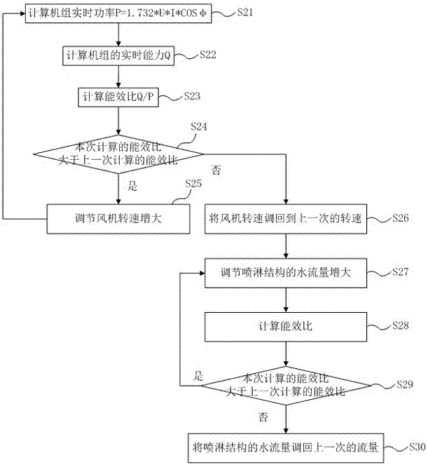
[0074] Embodiment 2. The difference between this embodiment and Embodiment 1 is: first adjust the fan speed, and then adjust the water flow of the spraying structure when the energy efficiency ratio no longer increases. The chiller control method with evaporative condenser in this embodiment specifically includes the following steps, see image 3 shown.

[0075] Step S21: The real-time power of the computer group P=1.732*U*I*COSφ.

[0076] Step S22: The real-time capability of the computer group Q=C*V*|T WI -T WO |.

[0077] Step S23: Calculate the energy efficiency ratio Q / P.

[0078] Steps S21-S23 are the same as those described in Embodiment 1, and reference may be made to Embodiment 1, and details will not be repeated here.

[0079] Step S24: Determine whether the energy efficiency ratio calculated this time is greater than the energy efficiency ratio calculated last time.

[0080] If yes, execute step S25.

[0081] If not, execute step S26.

[0082] Step S25: Adju...

Embodiment 3

[0104] Embodiment 3. The difference between this embodiment and Embodiment 1 is that: first adjust the water flow rate of the spray structure, and then adjust the fan speed when the energy efficiency ratio no longer increases. The chiller control method with evaporative condenser in this embodiment specifically includes the following steps, see Figure 4 shown.

[0105] Step S31: The real-time power of the computer group P=1.732*U*I*COSφ.

[0106] Step S32: Real-time capability Q=C*V*|T of the computer group WI -T WO |.

[0107] Step S33: Calculate the energy efficiency ratio Q / P.

[0108] Steps S31-S33 are the same as the descriptions of the first embodiment, and reference may be made to the first embodiment, and details are not repeated here.

[0109] Step S34: Determine whether the energy efficiency ratio calculated this time is greater than the energy efficiency ratio calculated last time.

[0110] If yes, execute step S35.

[0111] If not, execute step S36.

[011...


PUM


Abstract

The invention discloses a control method for a cooling water machine unit with an evaporative type condenser. The control method comprises the following steps: calculating real-time power, real-time capacity and energy efficiency ratio of the machine unit; judging whether the energy efficiency ratio calculated currently is greater than the energy efficiency ratio calculated previously; if the energy efficiency ratio calculated currently is greater than the energy efficiency ratio calculated previously, increasing the rotating speed of a fan or increasing the water flow rate of a spraying structure, calculating the energy efficiency ratio again, and comparing the energy efficiency ratio with the energy efficiency ratio calculated previously; and if the energy efficiency ratio calculated currently is not greater than the energy efficiency ratio calculated previously, regulating the rotating speed of the fan to the last rotating speed or regulating the water flow rate of the spraying structure to the last flow rate. Therefore, good rotating speed of the fan or good water flow rate of the spraying structure are obtained, the machine unit acquires high energy efficiency ratio, the energy efficiency ratio of the machine unit is improved, the purpose of saving energy is achieved, and energy saving control of the machine unit is realized.

Description

technical field [0001] The invention belongs to the technical field of air conditioning, and in particular relates to a control method for a chiller with an evaporative condenser. Background technique [0002] The market prospect of the plate-type evaporative condensing unit is optimistic due to the integration of the advantages of water cooling and air cooling. [0003] Existing units with plate-type evaporative condensers, general circulating water pumps and fans are fixed-frequency systems, and do not adjust spray density and wind speed. During the operation of the unit, the spray density and the frontal wind speed are fixed values. The energy efficiency EER of the unit is completely determined by the working conditions of the unit itself. If the unit does not operate under the optimal EER, it will not save energy. Contents of the invention [0004] The invention provides a control method for a chiller with an evaporative condenser, which improves the energy efficiency...

Claims


Application Information

Patent Timeline
Patent Type & Authority Applications(China)
IPC IPC(8): F25B49/02F24F11/00
CPCF25B49/02F25B2600/111F25B2600/2515F25B2700/151
Inventor 冷宇孙辉
Owner QINGDAO HAIER AIR CONDITIONING ELECTRONICS CO LTD
Why Eureka
Try Eureka