A control method of chiller with evaporative condenser
What is AI technical title?
AI technical title is built by PatSnap AI team. It summarizes the technical point description of the patent document.
An evaporative condenser and control method technology, which is applied in the field of air conditioning, can solve the problems of not saving energy, and achieve the effect of improving energy efficiency ratio and high energy efficiency ratio
Active Publication Date: 2021-09-21
QINGDAO HAIER AIR CONDITIONING ELECTRONICS CO LTD +1
View PDF8 Cites 0 Cited by
Summary
Abstract
Description
Claims
Application Information
AI Technical Summary
This helps you quickly interpret patents by identifying the three key elements:
Problems solved by technology
Method used
Benefits of technology
Problems solved by technology
During the operation of the unit, the spray density and the frontal wind speed are fixed values, and the energy efficiency EER of the unit is completely determined by the working conditions of the unit itself. The unit does not operate under the optimal EER and does not save energy.
Method used
Image
Click on the blue label to locate the original text in one second.
Reading with bidirectional positioning of images and text.
Examples
Embodiment 2
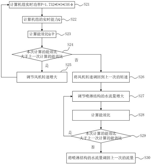
[0074] Embodiment 2. The difference between this embodiment and Embodiment 1 is: first adjust the fan speed, and then adjust the water flow of the spraying structure when the energy efficiency ratio no longer increases. The chiller control method with evaporative condenser in this embodiment specifically includes the following steps, see image 3 shown.
[0075] Step S21: The real-time power of the computer group P=1.732*U*I*COSφ.
[0076] Step S22: The real-time capability of the computer group Q=C*V*|T WI -T WO |.
[0077] Step S23: Calculate the energy efficiency ratio Q / P.
[0078] Steps S21-S23 are the same as those described in Embodiment 1, and reference may be made to Embodiment 1, and details will not be repeated here.
[0079] Step S24: Determine whether the energy efficiency ratio calculated this time is greater than the energy efficiency ratio calculated last time.
[0080] If yes, execute step S25.
[0081] If not, execute step S26.
[0082] Step S25: Adju...
Embodiment 3
[0104] Embodiment 3. The difference between this embodiment and Embodiment 1 is that: first adjust the water flow rate of the spray structure, and then adjust the fan speed when the energy efficiency ratio no longer increases. The chiller control method with evaporative condenser in this embodiment specifically includes the following steps, see Figure 4 shown.
[0105] Step S31: The real-time power of the computer group P=1.732*U*I*COSφ.
[0106] Step S32: Real-time capability Q=C*V*|T of the computer group WI -T WO |.
[0107] Step S33: Calculate the energy efficiency ratio Q / P.
[0108] Steps S31-S33 are the same as the descriptions of the first embodiment, and reference may be made to the first embodiment, and details are not repeated here.
[0109] Step S34: Determine whether the energy efficiency ratio calculated this time is greater than the energy efficiency ratio calculated last time.
[0110] If yes, execute step S35.
[0111] If not, execute step S36.
[011...
PUM
Abstract
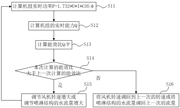
The invention discloses a chiller control method with an evaporative condenser. The real-time power, real-time capability, and energy efficiency ratio of the computer group are used to determine whether the energy efficiency ratio calculated this time is greater than the energy efficiency ratio calculated last time; if so, the fan speed is adjusted. Increase or adjust the water flow of the sprinkler structure to increase, recalculate the energy efficiency ratio, and compare it with the last calculated energy efficiency ratio; if not, adjust the fan speed back to the previous speed or reduce the water flow rate of the spray structure Revert back to the previous flow rate; thereby obtain a better fan speed or water flow rate of the spray structure, so that the unit can obtain a higher energy efficiency ratio, improve the energy efficiency ratio of the unit, achieve the purpose of energy saving, and realize the energy saving control of the unit.
Description
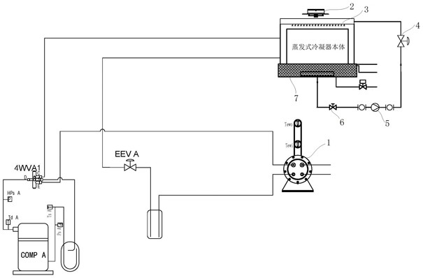
technical field [0001] The invention belongs to the technical field of air conditioning, and in particular relates to a control method for a chiller with an evaporative condenser. Background technique [0002] The market prospect of the plate-type evaporative condensing unit is optimistic due to the integration of the advantages of water cooling and air cooling. [0003] Existing units with plate-type evaporative condensers, general circulating water pumps and fans are fixed-frequency systems, and do not adjust spray density and wind speed. During the operation of the unit, the spray density and the frontal wind speed are fixed values. The energy efficiency EER of the unit is completely determined by the working conditions of the unit itself. If the unit does not operate under the optimal EER, it will not save energy. Contents of the invention [0004] The invention provides a control method for a chiller with an evaporative condenser, which improves the energy efficiency...
Claims
Application Information
Patent Timeline
Application Date:The date an application was filed.
Publication Date:The date a patent or application was officially published.
First Publication Date:The earliest publication date of a patent with the same application number.
Issue Date:Publication date of the patent grant document.
PCT Entry Date:The Entry date of PCT National Phase.
Estimated Expiry Date:The statutory expiry date of a patent right according to the Patent Law, and it is the longest term of protection that the patent right can achieve without the termination of the patent right due to other reasons(Term extension factor has been taken into account ).
Invalid Date:Actual expiry date is based on effective date or publication date of legal transaction data of invalid patent.
Patent Type & AuthorityPatents(China)
IPC IPC(8): F25B49/02
CPCF25B49/02F25B2600/111F25B2600/2515F25B2700/151
Inventor冷宇孙辉
OwnerQINGDAO HAIER AIR CONDITIONING ELECTRONICS CO LTD

