
Control device, water ring vacuum pump and control method thereof

A technology for control devices and vacuum pumps, which is applied in pump control, non-variable pumps, machines/engines, etc., can solve problems such as increased energy consumption, decreased efficiency of water ring vacuum pumps, and increased power consumption, so as to improve work efficiency, The effect of stabilizing the vacuum degree and saving electric energy

Inactive Publication Date: 2015-01-21
SHAANXI UNIV OF SCI & TECH +1
View PDF8 Cites 7 Cited by
  • Summary
  • Abstract
  • Description
  • Claims
  • Application Information

AI Technical Summary

Problems solved by technology

When the speed of the motor is constant, within a certain range of water level, the water ring formed by the high water level is large, and the water ring formed by the low water level is small, that is, when the water ring is too large, the power consumption will increase, so the water ring vacuum pump Efficiency decreases and power loss increases; at the same time, because the water supply of the water supply pipeline changes with the change of the working state, the vacuum degree of the water ring vacuum pump is affected to a certain extent, and the energy loss is increased at the same time.

Method used


Image

  • Control device, water ring vacuum pump and control method thereof
  • Control device, water ring vacuum pump and control method thereof
  • Control device, water ring vacuum pump and control method thereof

Examples


Embodiment Construction

[0019] The present invention will be described in detail below in conjunction with the accompanying drawings and specific embodiments.

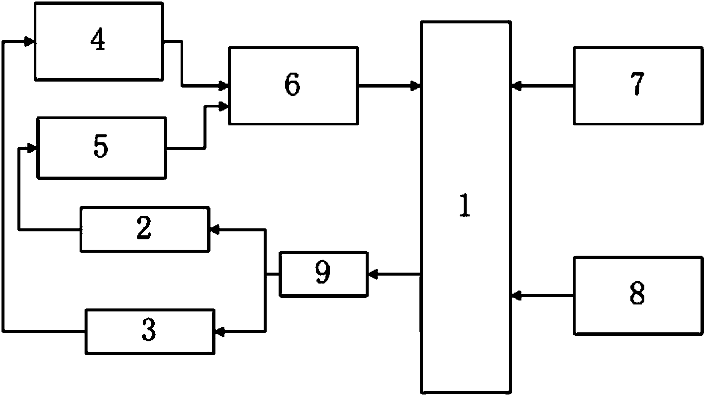
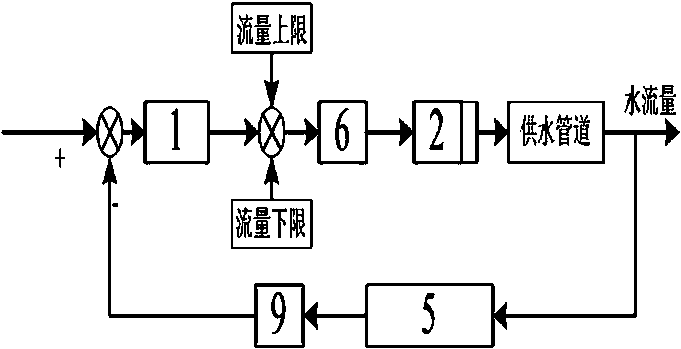
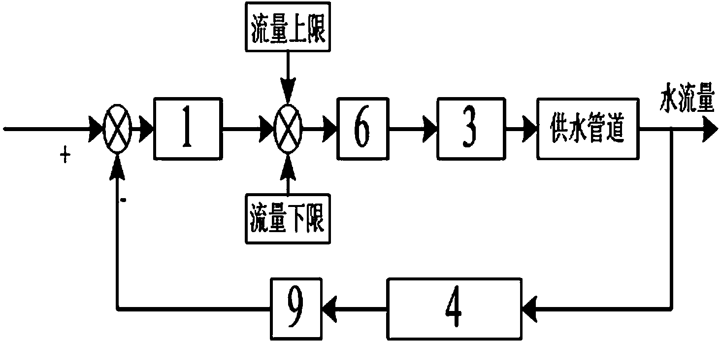
[0020] An embodiment of the present invention provides a control device, such as figure 1 As shown, the control device includes a control circuit, a vacuum degree sensor 4 arranged in the vacuum pump, a water flow sensor 5 arranged in the water supply pipeline, and an electromagnetic valve 2 arranged in the water supply pipeline; the control circuit includes a single-chip microcomputer 1, External reset clock circuit 7, A / D conversion circuit 6, serial communication circuit 8, D / A conversion circuit 9, described single-chip microcomputer 1 is connected with described solenoid valve 2 through D / A conversion circuit 9, and described external reset clock Circuit 7, serial communication circuit 8 are connected with single-chip microcomputer 1 respectively, and described vacuum degree sensor 4, water flow sensor 5 are connected with described sing...


PUM

PropertyMeasurementUnit
Resistanceaaaaaaaaaa
Capacitanceaaaaaaaaaa

Abstract

The invention discloses a control device which comprises a control circuit, a vacuum degree sensor disposed in the vacuum pump, a water flow sensor disposed in a water supply pipeline and an electromagnetic valve disposed in the water supply pipeline. The control circuit comprises a single-chip microcomputer, an external reset clock circuit, an A / D conversion circuit, a serial communication circuit, and a D / A conversion circuit. The external reset clock circuit and the serial communication circuit are respectively connected with the single-chip microcomputer. The single-chip microcomputer is connected with the electromagnetic valve through the D / A conversion circuit. The vacuum degree sensor and the water flow sensor is connected with the single-chip microcomputer through the A / D conversion circuit of the control circuit. The single-chip microcomputer controls the water flow in the water supply pipeline through the electromagnetic valve. The invention further discloses a water ring vacuum pump and a control method thereof. By the control device, the power consumption of the water ring vacuum pump is minimized, energy saving control of the water ring vacuum pump is achieved, power is saved while vacuum degree is stabilized, and the work efficiency of the water ring vacuum pump is increased.

Description

technical field [0001] The invention relates to the field of vacuum pump control, in particular to a control device, a water ring vacuum pump and a control method thereof. Background technique [0002] Water ring vacuum pumps usually use direct water supply in the actual industrial field use. A fixed valve controls the water supply volume, and then determines and controls the water level flowing into the pump body. This working method of water ring vacuum pumps cannot make the size of the water ring between The best working condition of the vacuum pump. When the speed of the motor is constant, within a certain range of water level, the water ring formed by the high water level is large, and the water ring formed by the low water level is small, that is, when the water ring is too large, the power consumption will increase, so the water ring vacuum pump Efficiency decreases and power loss increases; at the same time, because the water supply of the water supply pipeline chan...

Claims


Application Information

Patent Timeline
IPC IPC(8): F04D27/00
CPCF04C28/00F04C28/08
Inventor 孟彦京赵丹段明亮陈景文马汇海朱纳
Owner SHAANXI UNIV OF SCI & TECH
Learn More