Ethernet switch and port polling system and polling method thereof

A polling method and switch technology, applied in transmission systems, digital transmission systems, data exchange networks, etc., can solve problems such as affecting the life of switches and taking a long time to restart switches, and achieve the effect of ensuring real-time requirements.

Active Publication Date: 2015-11-18
BEIJING BROADWIT TECH
View PDF5 Cites 7 Cited by
  • Summary
  • Abstract
  • Description
  • Claims
  • Application Information

AI Technical Summary

Problems solved by technology

[0003] The purpose of the present invention is to overcome the problems in the prior art that it takes a long time to restart the switch due to the need to power off the switch to achieve energy saving, and frequent power failures affect the life of the switch, and provides a method that only polls the port connection status of the switch and closes it in time. Ethernet switch port polling system for sending and receiving functions without connected ports

Method used


Image

  • Ethernet switch and port polling system and polling method thereof
  • Ethernet switch and port polling system and polling method thereof
  • Ethernet switch and port polling system and polling method thereof

Examples


Embodiment 1

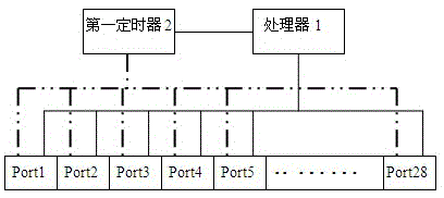
[0030] Embodiment 1: as figure 1 As shown, the present embodiment takes a switch with 28 ports (Port1-Port28) as an example, and provides an Ethernet switch port polling system, including a first timer 2, which is set with a port polling period T1 , which is used to sequentially perform polling timing with a duration of T1 on the 28 ports of the switch, and the port that is polling and timing is the current timing port; figure 1 The dotted line connecting the first timer 2 and the 28 ports of the switch only means that the first timer 2 can provide polling timing for the 28 ports of the switch, and does not represent a real connection.

[0031] A processor 1 is used for opening or maintaining the sending and receiving function of the current timing port when the current timing port polling period T1 starts; the processor 1 is also used for reading during the current timing port polling period T1 Get the connection status of the current timing port; when the port polling perio...

Embodiment 2

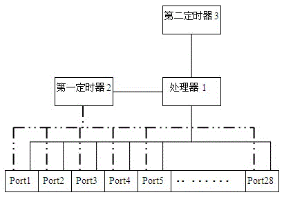
[0038] Embodiment 2: as figure 2 As shown, this embodiment also takes a switch with 28 ports (Port1-Port28) as an example, but the difference between this embodiment and Embodiment 1 is that in this embodiment, the port polling system includes a first On the basis of the timer 2 and a processor 1, it also includes a second timer 3, the second timer 3 is provided with a system polling period T2, and in each system polling period T2, the first The timer 2 and the processor 1 only poll each port of the switch once, T2≥28*T1, the system polling cycle T2 can be changed or set by the user again, when the user thinks that T2=28*T1 When the setting of the polling frequency of the switch port is too fast, the T2 time can be appropriately lengthened, because in each system polling cycle T2, the first timer 2 and the processor 1 only The port is polled once. Therefore, when T2>N*T1, processor 1 will take a rest of T2-N*T1 in each T2 cycle without polling any port.

[0039] Such as F...

Embodiment 3

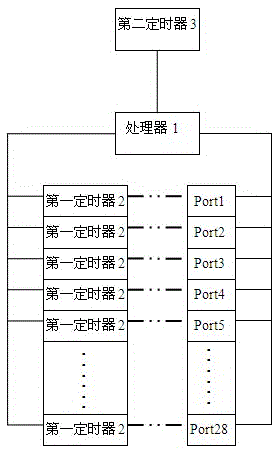
[0047] Embodiment 3: as image 3 As shown, this embodiment also takes a switch with 28 ports (Port1-Port28) as an example, but the difference between this embodiment and Embodiment 2 is that the port polling system includes a processor 1 and a second timer device 3, and also includes 28 first timers 2, and the 28 first timers 2 are in one-to-one correspondence with the 28 ports of the switch, that is, when Port1 is the current timing port, the first first timer corresponding to it A timer 2 counts for it; after the first first timer 2 finishes timing, Port2 becomes the current timing port, and the second first timer 2 is for Port2 to time; when the second first timer 2 After the timing ends, Port3 becomes the current timing port, and now the third first timer 2 is Port3 timing; and so on, until Port28 is the current timing port, the twenty-eighth first timer 2 is the round of Port28. query timing.

[0048] At the same time, since each switch port is correspondingly provided ...


PUM


Abstract

The invention relates to the field of Ethernet switch energy saving, and particularly relates to an Ethernet switch and a port polling system and a polling method thereof. A first timer is arranged to carry out timing for the ports of a switch in a polling way, a processor reads the connection state of the current timing port within the time of port polling timing, and therefore, opening and closing of the sending and receiving function of the ports can be controlled according to the connection state of the ports at the end of port polling timing, and energy saving control on the switch is realized. Meanwhile, a second timer is provided to control the polling frequency of each port of the switch, so that opening and closing of the sending and receiving function of the ports can be controlled at appropriate time according to the connection state of the ports. Therefore, real-time demand of the normal functions of the ports can be effectively ensured while energy saving control is achieved.

Description

technical field [0001] The invention relates to the field of energy saving of Ethernet switches, in particular to an Ethernet switch and its port polling system and polling method. Background technique [0002] The energy-saving design of industrial equipment is an extremely frequently used and highly respected technology. Due to the differences in industrial Ethernet switch equipment and functional requirements, the energy-saving methods adopted also have their own characteristics. In the field of switch energy saving, it is widely used that the switch detects its network traffic in real time, starts a timer when the detected network traffic is empty, and automatically cuts off the power of the switch when no network traffic is detected when the timer expires. This intelligent power-off energy-saving method with a timer can effectively prevent the user from frequently turning on or off the switch during normal use. However, although this method of energy saving by cutting ...

Claims


Application Information

Patent Timeline
IPC IPC(8): H04L12/931
CPCH04L49/10H04L49/40
Inventor 孟令勇谢勇张继光许伟李淼
Owner BEIJING BROADWIT TECH
Why Eureka
Try Eureka