Pivoting support bearing integral holder and process thereof

A technology for slewing ring bearings and production processes, which is applied to bearing components, shafts and bearings, mechanical equipment, etc., and can solve the problems of lower bearing assembly performance requirements, high manufacturing costs, and cumbersome assembly processes, etc.

Active Publication Date: 2009-07-22
SHANDONG GOLDEN EMPIRE PRECISION MACHINERY TECH CO LTD
View PDF0 Cites 10 Cited by
  • Summary
  • Abstract
  • Description
  • Claims
  • Application Information

AI Technical Summary

Problems solved by technology

At present, there are a few manufacturers in China who use split and multi-piece assembly to manufacture and assemble large bearing cages, which reduces the assembly performance requirements of the bearings, and the manufacturing cost is high and the assembly process is cumbersome.

Method used


Image

  • Pivoting support bearing integral holder and process thereof
  • Pivoting support bearing integral holder and process thereof
  • Pivoting support bearing integral holder and process thereof

Examples


Embodiment 1

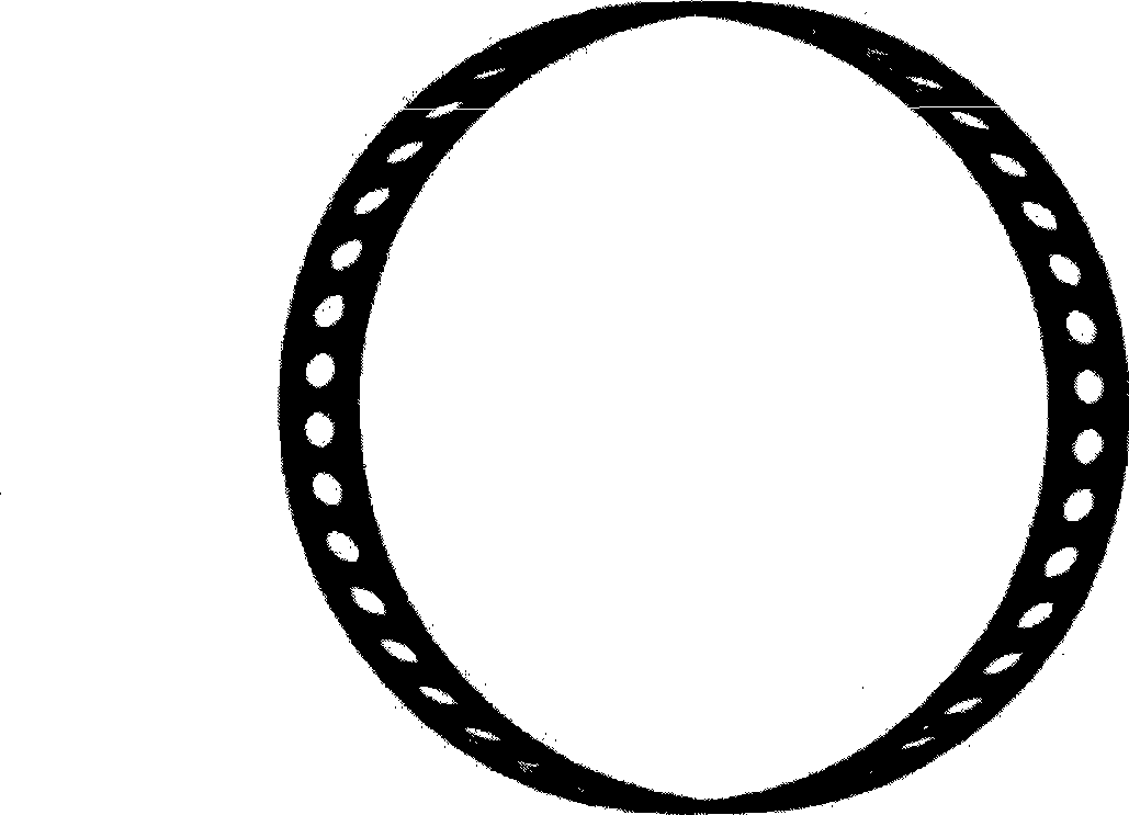
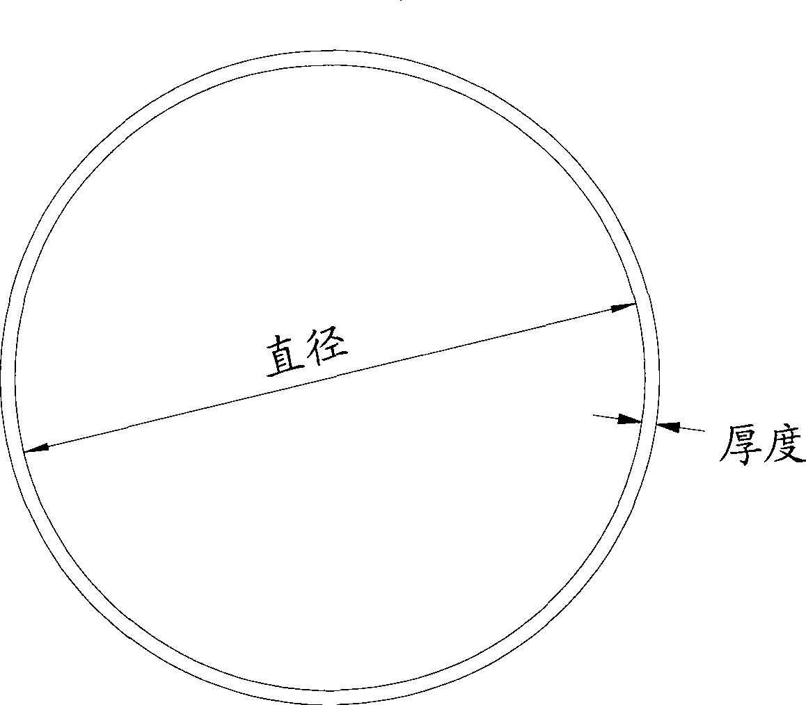
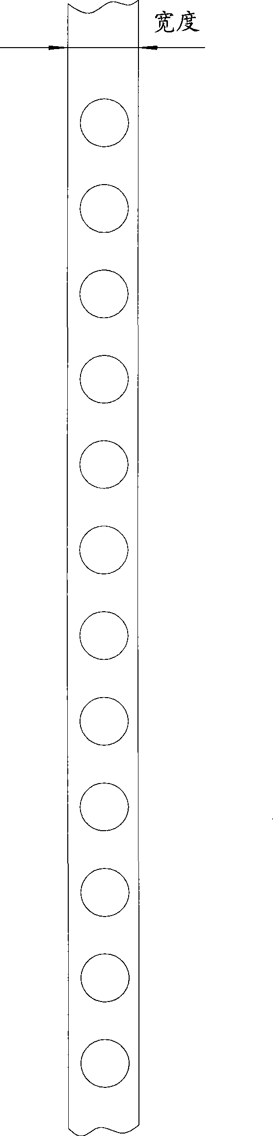
[0039] This embodiment is a production process for producing an integral cage of a slewing ring bearing with a diameter of 2000 mm, a width of 55 mm, and a thickness of 6 mm. Such as figure 1 as shown, figure 1 It is a schematic diagram of the overall appearance of the integral cage of the slewing ring bearing. figure 2 It is a schematic front view of the integral cage of the slewing ring bearing. The diameter and thickness described in the present invention are as figure 2 shown. image 3 It is a schematic diagram of the expansion of the integral cage of the slewing ring bearing. The width described in the present invention is as follows image 3 shown.

[0040] This embodiment includes the following steps:

[0041] (1) cut off the raw steel

[0042] The raw steel in this embodiment is a cold-drawn steel made of 40CrMnMo. The round steel of the corresponding size and diameter is processed by cold drawing to become a flat blank with a slight grinding allowance, and t...

Embodiment 2

[0076] The preparation process of this embodiment is the same as that of Example 1, the difference is that:

[0077] Step (5) Rough rounding

[0078] In this embodiment, not only the non-equal angle rounding structure is used for rounding in the rough rounding, but the non-equal angle rounding structure includes one active roller and two passive rollers, and the distance between the contact points of the two passive rollers and the integral cage of the bearing is Twice the center-to-center distance of two adjacent circular holes.

[0079] Also, see Figure 8 , in the process of rounding, there are also adjustment wheel sets 13 on both sides of the non-equal angle rounding structure, and the adjustment wheel sets 13 can further limit the deformation of the overall cage of the bearing during the rounding process, and the roundness of the overall cage of the bearing And flatness is further improved. The working principle of the adjustment wheel set 13 is similar to that of the...


PUM


Abstract

The invention discloses an integral cage of a slewing bearing. Diameter of the integral cage is over 1000mm, width thereof is over 40mm, and thickness thereof is 4-8mm. The invention further discloses a production process of the integral bearing cage. The production process comprises the following steps: a) cutting off raw steel; b) abrasive machining on surface; c) punching round holes; d) abrasive machining on the punched round holes; e) roughly rounding, wherein, a non-equiangular rounding structure is employed for rounding, the non-equiangular rounding structure comprises a driving roller and two driven rollers, and the distance between contact points of the two driven rollers and the integral bearing cage is less than or equal to twice of the center distance between two adjacent circular holes; f) welding; and g) finely rounding. The production process can be adopted to produce large integral bearing cages, and the obtained large integral bearing cages have relatively simple integral molding and assembly process.

Description

technical field [0001] The invention relates to an integral cage of a slewing support bearing and a production process thereof, belonging to the field of bearings. Background technique [0002] The development and utilization of new energy has increasingly become a focus of production and research. In nature, the wind is a renewable, non-polluting and huge reserves of energy. With the global warming and energy crisis, all countries are stepping up the development and utilization of wind power to minimize the emission of carbon dioxide and other greenhouse gases and protect the earth we depend on for survival. [0003] The slewing ring bearing cage used in wind power generation equipment has large volume, high precision, special structure, harsh service conditions and application environment, and basically loses the possibility of disassembly and repair once it is installed in the equipment. At present, there are a few manufacturers in China who manufacture and assemble lar...

Claims


Application Information

Patent Timeline
Patent Type & Authority Applications(China)
IPC IPC(8): F16C33/42F16C33/44
Inventor 郑广辉王树杞
Owner SHANDONG GOLDEN EMPIRE PRECISION MACHINERY TECH CO LTD
Why Eureka
Try Eureka