Backlash elimination structure of transmission mechanism

A transmission mechanism and backlash technology, which is applied to mechanical equipment, components with teeth, belts/chains/gears, etc., can solve problems such as difficult mechanism rigidity, limited space or complex structure, and effects of backlash elimination

Inactive Publication Date: 2009-07-22
崴立机电股份有限公司
View PDF0 Cites 8 Cited by
  • Summary
  • Abstract
  • Description
  • Claims
  • Application Information

AI Technical Summary

Problems solved by technology

However, when the above-mentioned gear moves with the entire feed device as the main body, not only the swing arm is too large, resulting in space restrictions on the assembly of the overall transmission

Method used


Image

  • Backlash elimination structure of transmission mechanism
  • Backlash elimination structure of transmission mechanism
  • Backlash elimination structure of transmission mechanism

Examples


Embodiment Construction

[0018] The above and other technical features and advantages of the present invention will be described in more detail below in conjunction with the accompanying drawings.

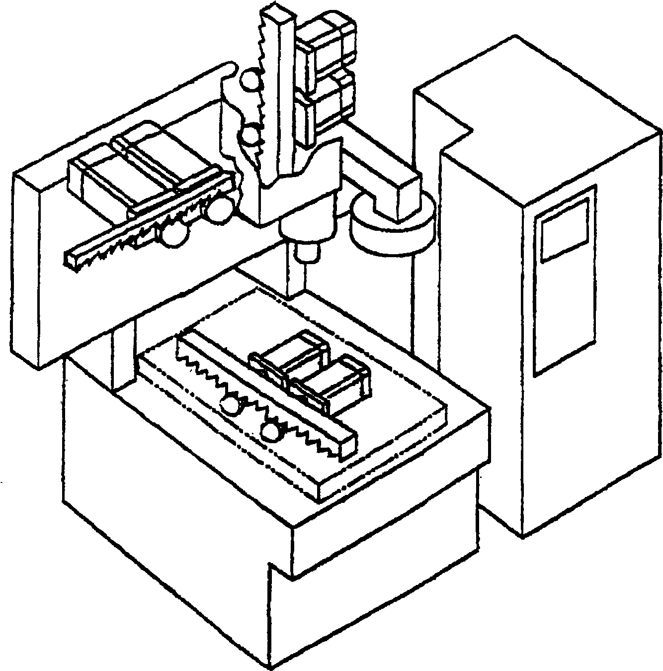
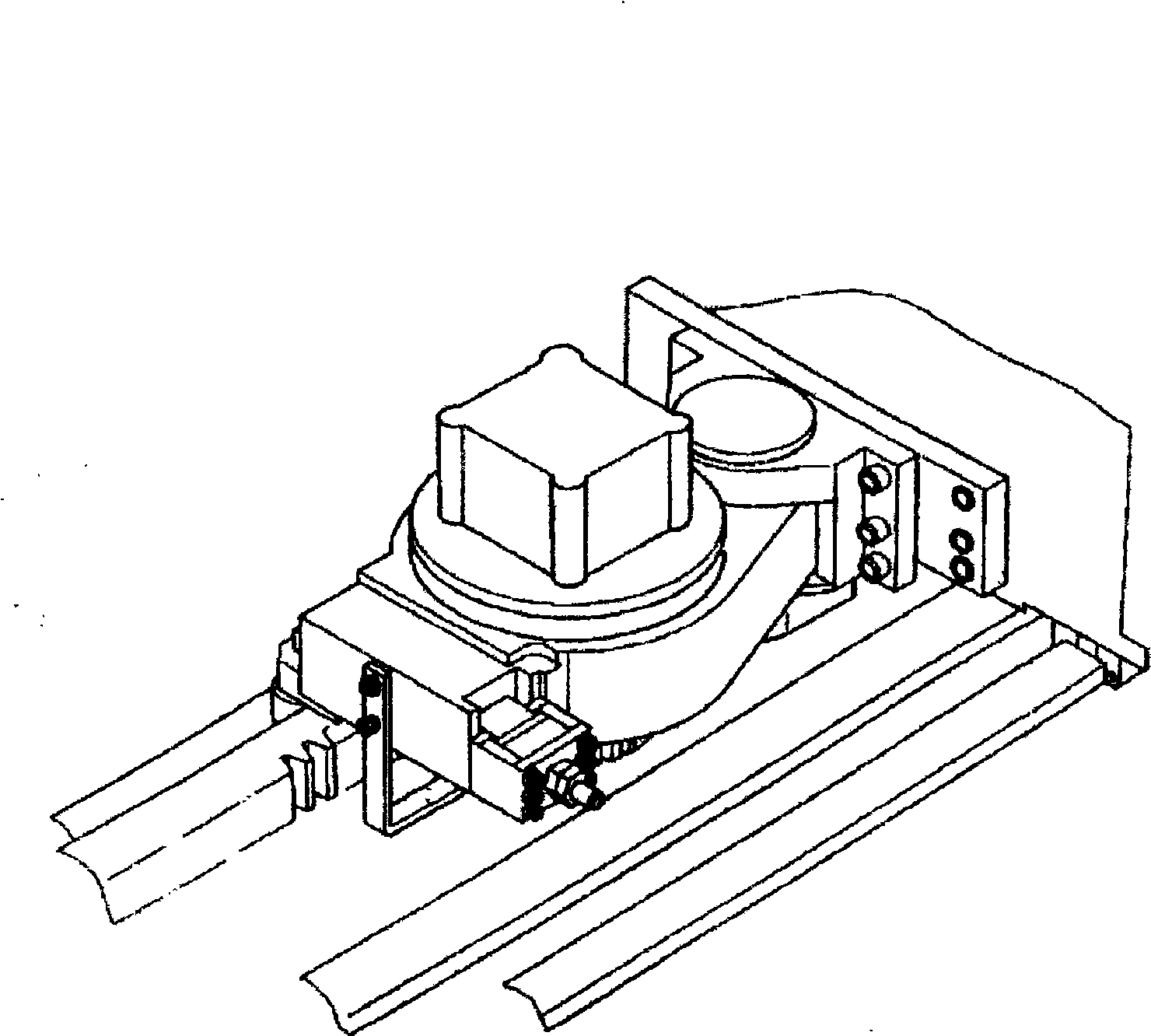
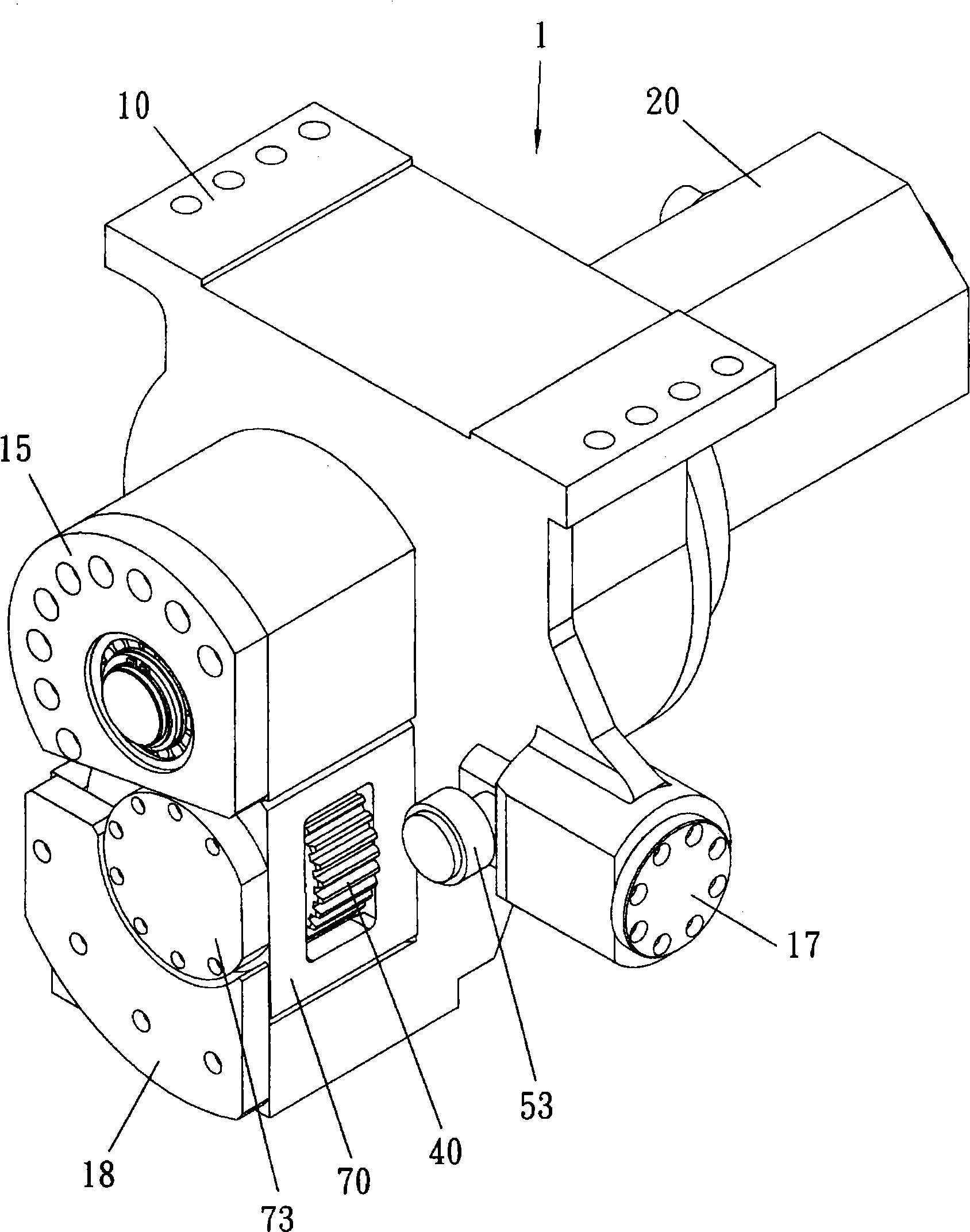
[0019] see Figure 3 ~ Figure 7 As shown, the backlash elimination structure of the transmission mechanism of the present invention is composed of a mechanism body (10), a motor (20), a driving gear (30), a driven gear (40), an elastic unit (50), and a buffer unit ( 60) and other components form a transmission mechanism (1), so that the transmission mechanism (1) can move on a straight or curved rack (2), wherein:

[0020] The mechanism body (10) is provided with a plurality of accommodation parts (11, 12, 13, 14) on its peripheral inner edge respectively, and its first accommodation part (11) is located at the center and is in the shape of In the through-hole structure in the stage configuration, the inner side is for accommodating the driving gear (30), and a cover plate (15) is locked to fix it. The s...


PUM


Abstract

The invention provides a tooth space eliminating mechanism of a driving mechanism. The invention relates to a driving mechanism which is composed of a mechanism body, a motor, a driving gear, a driven gear, an elastic unit, and the like and can move along and be meshed with the rack. Essentially, the elastic unit set is arranged at the appropriate position of one side of the driven gear adjacent to the mechanism body, so that the elastic unit can apply an elastic force to the driven gear and the force application direction is coincided with the slant angle positioned between the driving gear and the rack, and furthermore, the driven gear can constantly and simultaneously move towards the driving gear and the rack, thus eliminating the tooth space.

Description

technical field [0001] The present invention relates to a linear and arc-shaped rack transmission structure, in particular to a structure aimed at eliminating the backlash generated during rack transmission and promoting the meshing stability of the rack transmission. Background technique [0002] At present, the transmission and movement of many industrial machinery are achieved by combining various tooth shapes, and there are quite a variety of tooth-shaped mechanisms, such as the combination of gears, lead screws, racks, etc., which are transmitted through the combination of tooth-shaped objects. power. However, the biggest disadvantage of the application of the toothed member in the transmission mechanism is the generation of backlash. When the gear and the rack are meshed, the gap between the teeth exists. The reason for the backlash may come from manufacturing tolerances, wear, or it may be designed to reduce the friction of the transmission. However, for transmissio...

Claims


Application Information

Patent Timeline
IPC IPC(8): F16H55/18F16H55/28
Inventor 关永昌
Owner 崴立机电股份有限公司
Why Eureka
Try Eureka