Kinetic energy machine (unit)

A kinetic energy machine and mechanical kinetic energy technology, applied in the field of transmission equipment and mechanical rotation, can solve the problems of low energy consumption and high speed.

Inactive Publication Date: 2009-07-29
江绍和
View PDF0 Cites 2 Cited by
  • Summary
  • Abstract
  • Description
  • Claims
  • Application Information

AI Technical Summary

Problems solved by technology

The above two forms of energy-saving products cannot fundamentally solve the problem of running equipment with low energy consumption, high speed, and requiring huge energy,

Method used


Image

  • Kinetic energy machine (unit)
  • Kinetic energy machine (unit)
  • Kinetic energy machine (unit)

Examples


Embodiment Construction

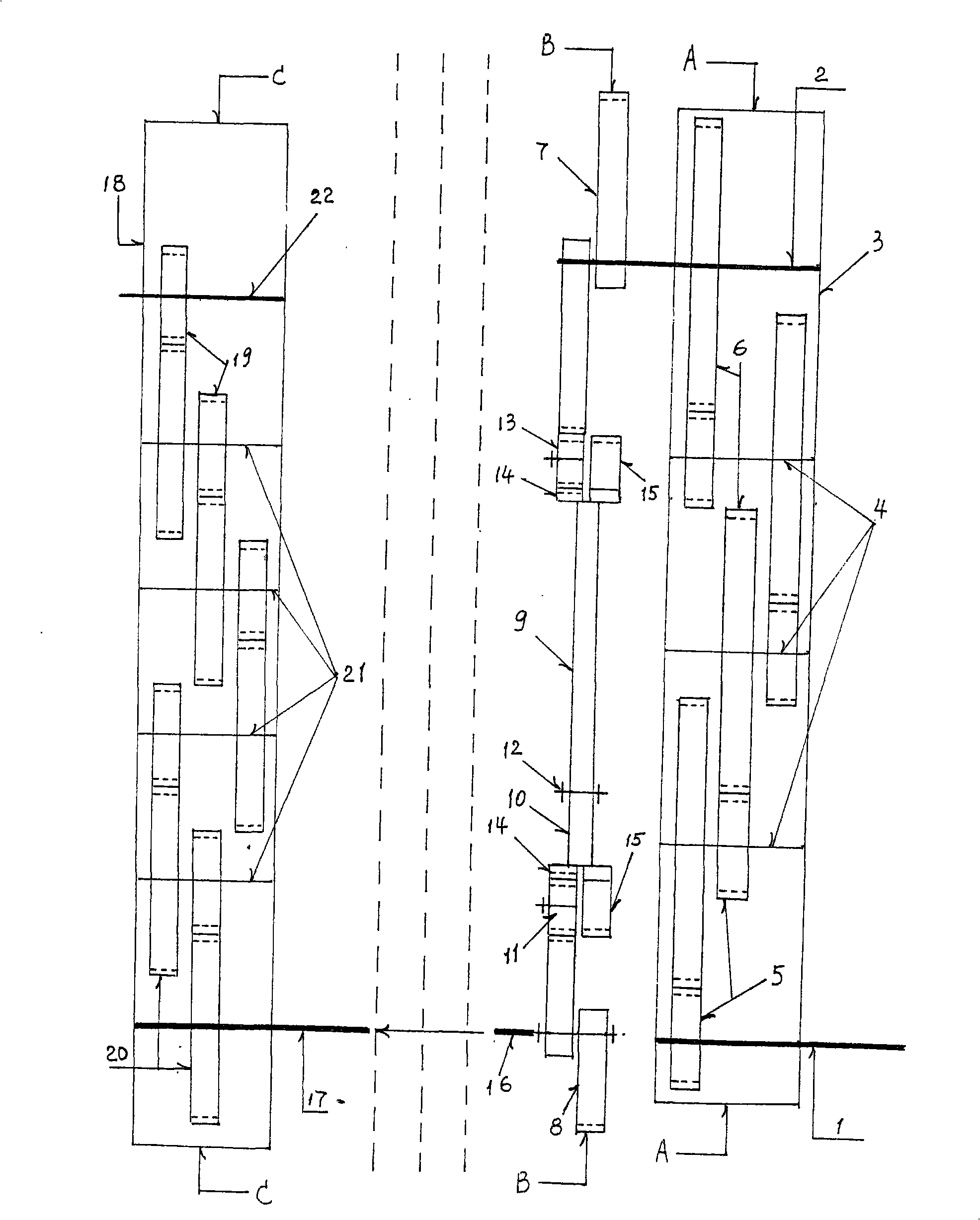
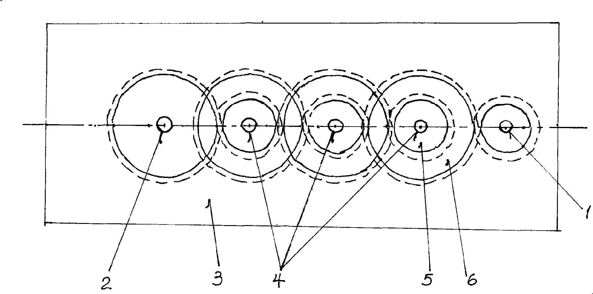
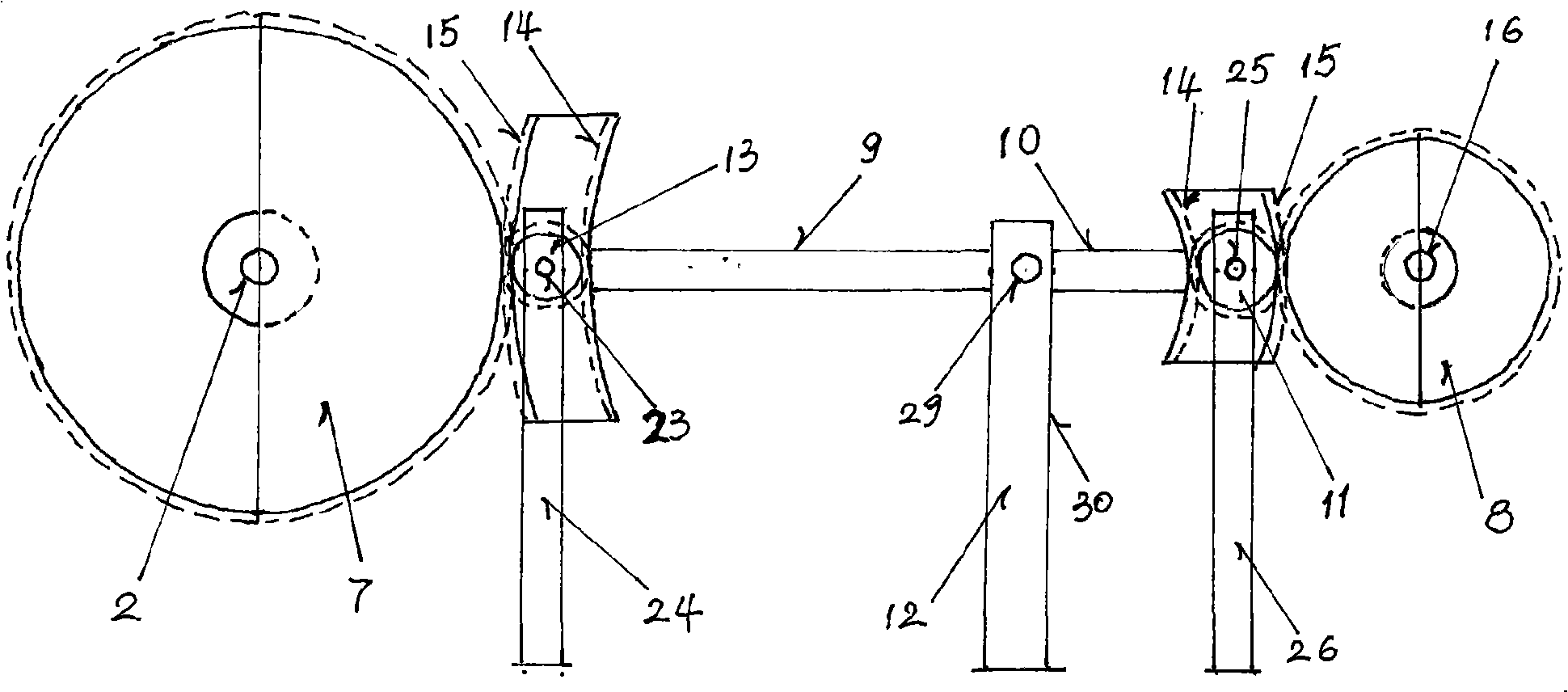
[0012] Now describe as follows in conjunction with the embodiment of kinetic energy machine (group):

[0013] The present invention is mainly composed of four parts, a reduction box, a lever linkage device, a connector and a speed-up box. The reduction box includes a power input shaft 1, a power output shaft 2, a wheel shaft 4, a small wheel 5 respectively assembled on the input shaft 1 and the wheel shaft 4, a large wheel 6 installed on the wheel shaft 4 and the output shaft 2, and a box for positioning the wheel shaft. Body wall panels 3. The lever linkage device comprises the driving wheel 7 that is installed on the output shaft 2 outer end (the driving wheel end 31 of the connector 16) and the two semicircular wheels are dislocated and assembled, and is assembled on the speed-up box driving shaft 17 outer end (the driving wheel end 31 of the connector 16). The driven wheel 8 that is also formed by dislocation of two semicircular wheels on the driving wheel end 32), and th...


PUM


Abstract

A kinetic energy machine (set) belongs to an energy-saving rotation and transmission device, and comprises a reduction gearbox and lever linkage devices; n groups of lever linkage devices are connected with each other by a connector to form linkage, while major semiaxis of a lever is N times longer than the semi-minor axis of the lever; furthermore, due to the linkage among a driving wheel, a driven wheel, an inner side wheel, an outer side wheel, a reverse wheel and a directional wheel, the major semiaxis and the semi-minor axis of the lever pry up and down at low uniform speed around a fulcrum, thus generating mechanical kinetic energy which is obtained by multiplying input power with N, and outputting the mechanical kinetic energy through a driven shaft end of a speed-raising box.

Description

technical field [0001] The invention relates to mechanical rotating and transmission equipment, in particular to energy-saving rotating and transmission equipment. Background technique [0002] Up to now, the energy-saving products on the market include gourd-style labor-saving equipment and technical equipment to reduce energy consumption and improve energy efficiency. For example, the gourd uses multiple decelerations to transfer heavier objects with less force to save labor. However, technical equipment that reduces energy consumption and improves energy use efficiency simply starts and realizes reduction of energy consumption or improvement of its use efficiency. The above two forms of energy-saving products cannot fundamentally solve the problem of running equipment with low energy consumption, high speed, and requiring huge energy, and none of them can be used continuously with only a small amount of power. It is a mechanical energy-saving equipment that continuously ...

Claims


Application Information

Patent Timeline
IPC IPC(8): F16H37/12
Inventor 江绍和
Owner 江绍和
Why Eureka
Try Eureka