Method for arranging driver auxiliary system based on ultrasonic wave and ultrasonic sensor

A driver assistance, ultrasonic technology, applied in the re-radiation of sound waves, radio wave measurement systems, transmission systems, etc., can solve the problems of increased cable laying costs, increased laying costs, increased wiring harness costs, etc., and achieves less plugging. Contact, installation time reduction, line saving effect

Active Publication Date: 2009-07-29
ROBERT BOSCH GMBH
View PDF0 Cites 4 Cited by
  • Summary
  • Abstract
  • Description
  • Claims
  • Application Information

AI Technical Summary

Problems solved by technology

In addition, in the case of twelve ultrasonic sensors, which are not uncommon in motor vehicles, the cabling expenditure will increase significantly, which not only leads to an increase in the cost of the motor vehicle wiring harness, but also increases the cost of laying
Additional equipment with a parking system would therefore add unnecessary costs, since many sensors with individual point-to-point connections would have to be installed
In addition, a large number of wires also means a large number of electrical connections, which can be easily damaged in harsh conditions in a motor vehicle

Method used


Image

  • Method for arranging driver auxiliary system based on ultrasonic wave and ultrasonic sensor
  • Method for arranging driver auxiliary system based on ultrasonic wave and ultrasonic sensor
  • Method for arranging driver auxiliary system based on ultrasonic wave and ultrasonic sensor

Examples


Embodiment Construction

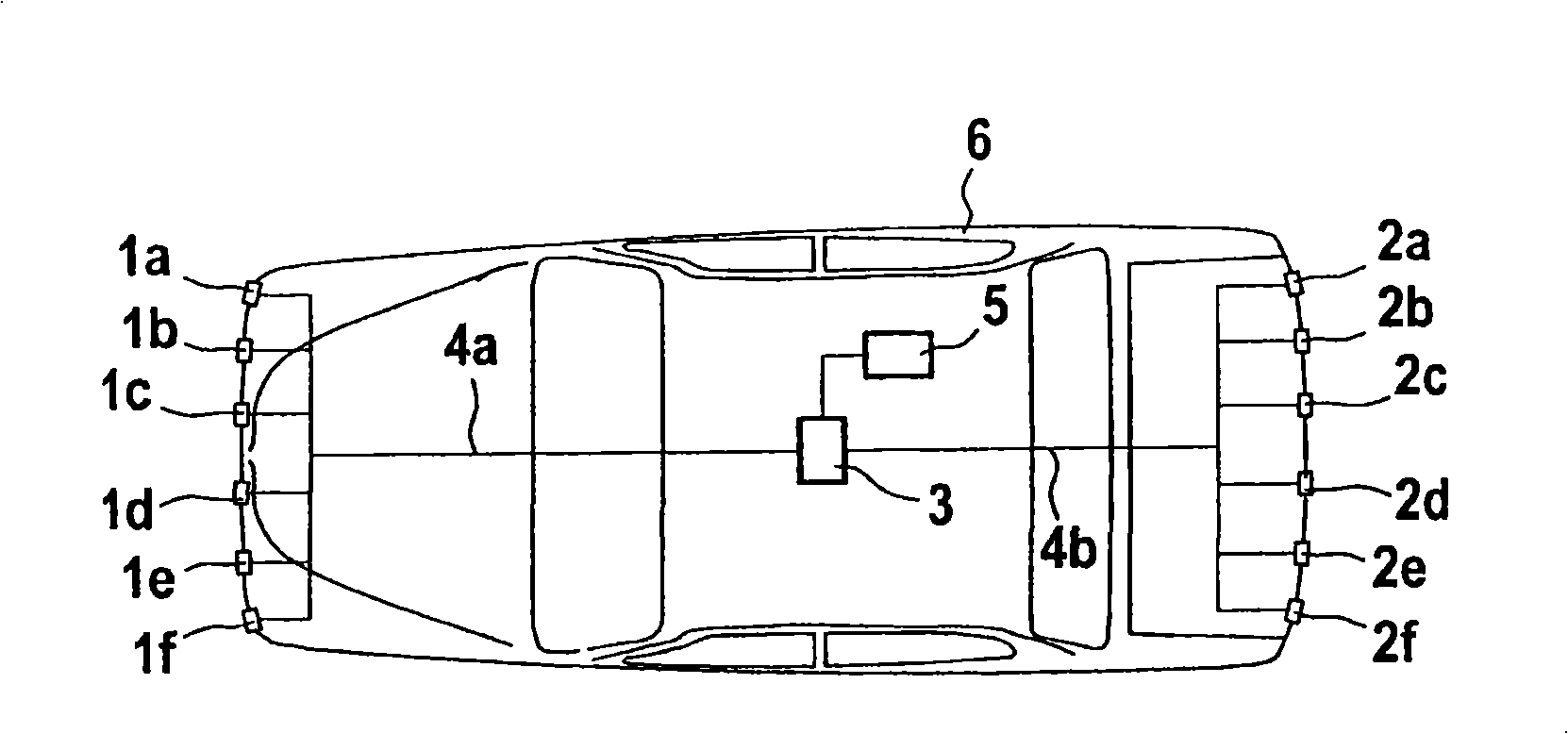
[0015] figure 1 is a block diagram of an ultrasonic sensor-based driver assistance system consisting of ultrasonic sensors 1a, 1b, 1c, 1d, 1e and 1f at the front of the vehicle and ultrasonic sensors 2a, 2b, 2c, 2d at the rear of the vehicle , composed of 2e and 2f. All ultrasonic sensors 1a, 1b, 1c, 1d, 1e and 1f and 2a, 2b, 2c, 2d, 2e and 2f are connected to central control unit 3 via a common electronic bus system 4a and 4b. In order to configure the control unit 3 , the communication unit 5 is connected to an external reader, not shown here, in order to transmit the identification code provided on the ultrasonic sensor to the central control unit 3 . Due to the bus structure of all ultrasonic sensors 1a, 1b, 1c, 1d, 1e and 1f as well as 2a, 2b, 2c, 2d, 2e and 2f, motor vehicle 6 requires significantly less effort for cabling than conventional systems, In conventional systems, all ultrasonic sensors are connected to a central control unit via point-to-point connections. ...


PUM


Abstract

The present invention relates to a method for configuring a driver auxiliary system based on an ultrasonic wave, wherein the driver auxiliary system having a plurality of ultrasonic sensors arranged at various positions of an automobile and at least a control unit, the ultrasonic sensors have absolute identification codes capable of being identified exteriorly, and the identification codes may beread electronically. According to the present invention, firstly a corresponding ultrasonic sensor is mounted and is connected with the control unit through an electronic bus system. Then, all identification codes are read out in given sequence by an external reader, and the external reader transmits the identification codes to the control unit, such that a controller implements a correspondence between the identification codes and the positions on the automobile.

Description

field of invention [0001] The invention relates to a method for configuring an ultrasound-based driver assistance system with a plurality of ultrasound sensors and at least one control unit, the ultrasound sensors being installed at different points in a motor vehicle, here , these ultrasonic sensors have an externally identifiable absolute identification code which can also be read electronically. Background technique [0002] Ultrasound-based driver assistance systems, such as parking assistance functions in motor vehicles, require a plurality of different ultrasonic sensors for distance detection in order to be able to calculate the distances of different parts of the vehicle in different directions from obstacles. A typical system configuration of an ultrasound-based parking assistant has at least two, often six, and sometimes more ultrasound sensors per bumper, which operate according to the echo-distance principle. In assisted driving, in order to reasonably distribut...

Claims


Application Information

Patent Timeline
Patent Type & Authority Applications(China)
IPC IPC(8): G01S15/93G01S15/08G01S15/931
CPCH04L61/2038G01S7/52004G01S15/931H04L2012/40273G01S15/87G01S2015/938H04L61/5038
Inventor M·塞特A·克洛茨T·特雷普托M·黑林D·施密德M·格拉赫P·拉普斯B·赫德
Owner ROBERT BOSCH GMBH
Why Eureka
Try Eureka