Supercharge Your Innovation With Domain-Expert AI Agents!

Centralization type light change circuit for LED illuminating system

A technology of LED lighting and dimming circuits, which is applied to lighting devices, lamp circuit layout, light sources, etc., can solve the problems of complex circuits, reduced reliability, and high cost, and achieve reduced harmonic pollution, reduced conduction loss, and reduced volume effect

Active Publication Date: 2009-07-29
INVENTRONICS HANGZHOU
View PDF0 Cites 29 Cited by
  • Summary
  • Abstract
  • Description
  • Claims
  • Application Information

AI Technical Summary

Problems solved by technology

Since the LED power supply adopts high-efficiency, wide-range input voltage AC / DC high-frequency switching power supply, the traditional linear adjustment of input voltage or phase-controlled voltage regulation can no longer adjust the output voltage or current, and cannot realize the brightness adjustment of LED lights.
At present, there are many ways of dimming: some use automatic timing dimming in the LED driver, that is, when the lamp is on for a certain period of time, the brightness will be lowered. This control method requires each LED lamp to have an ambient brightness detection device. And timing dimming circuit, and the turn-on, turn-off and dimming time of each LED light are not uniform, and the entire lighting system is not controllable
It is also possible to add a control circuit that can receive wireless signals or power carrier signals to the power supply, and then send signals through the central controller to centrally control the brightness of the LED lighting system, but this method is costly, complicated and less reliable.

Method used


Image

  • Centralization type light change circuit for LED illuminating system
  • Centralization type light change circuit for LED illuminating system
  • Centralization type light change circuit for LED illuminating system

Examples


Embodiment Construction

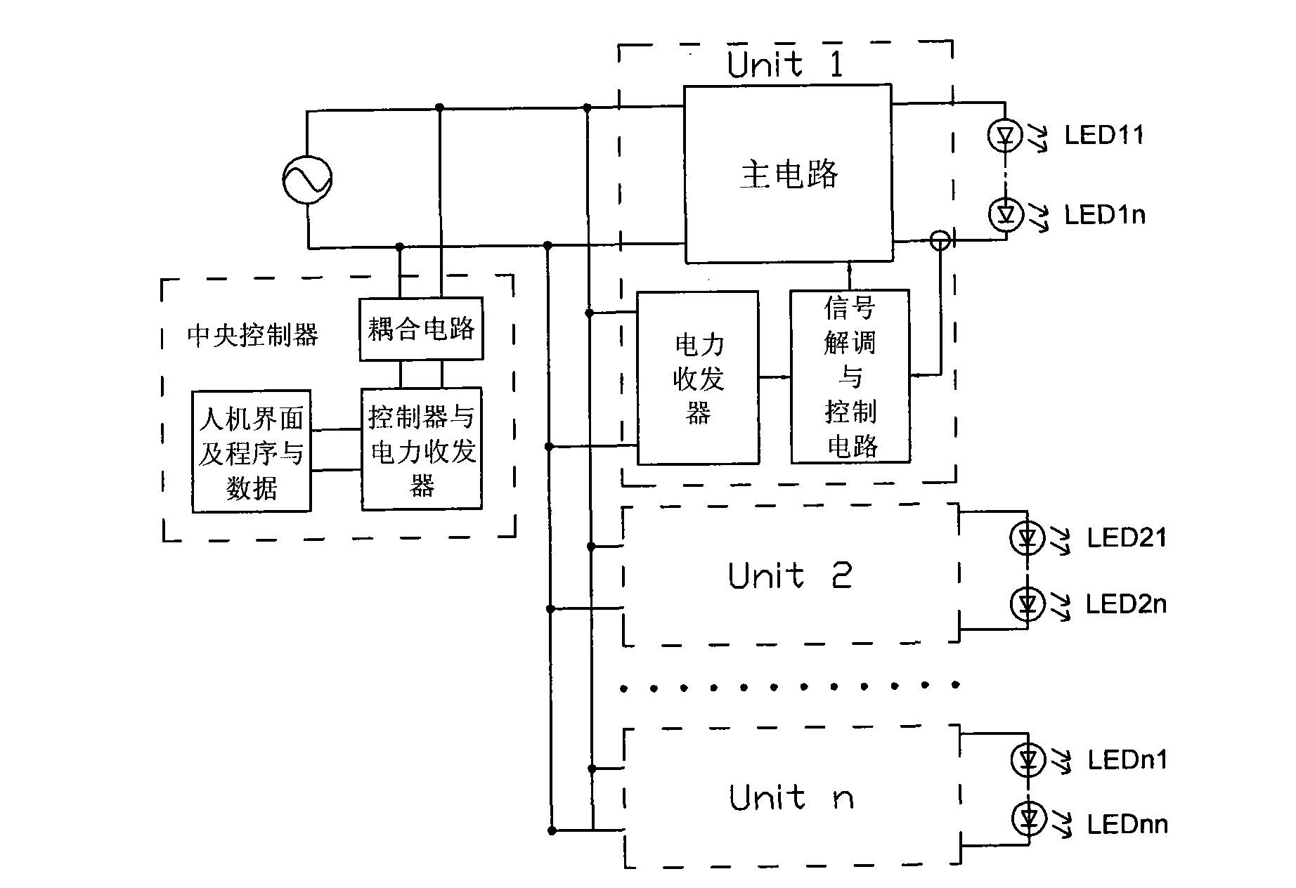
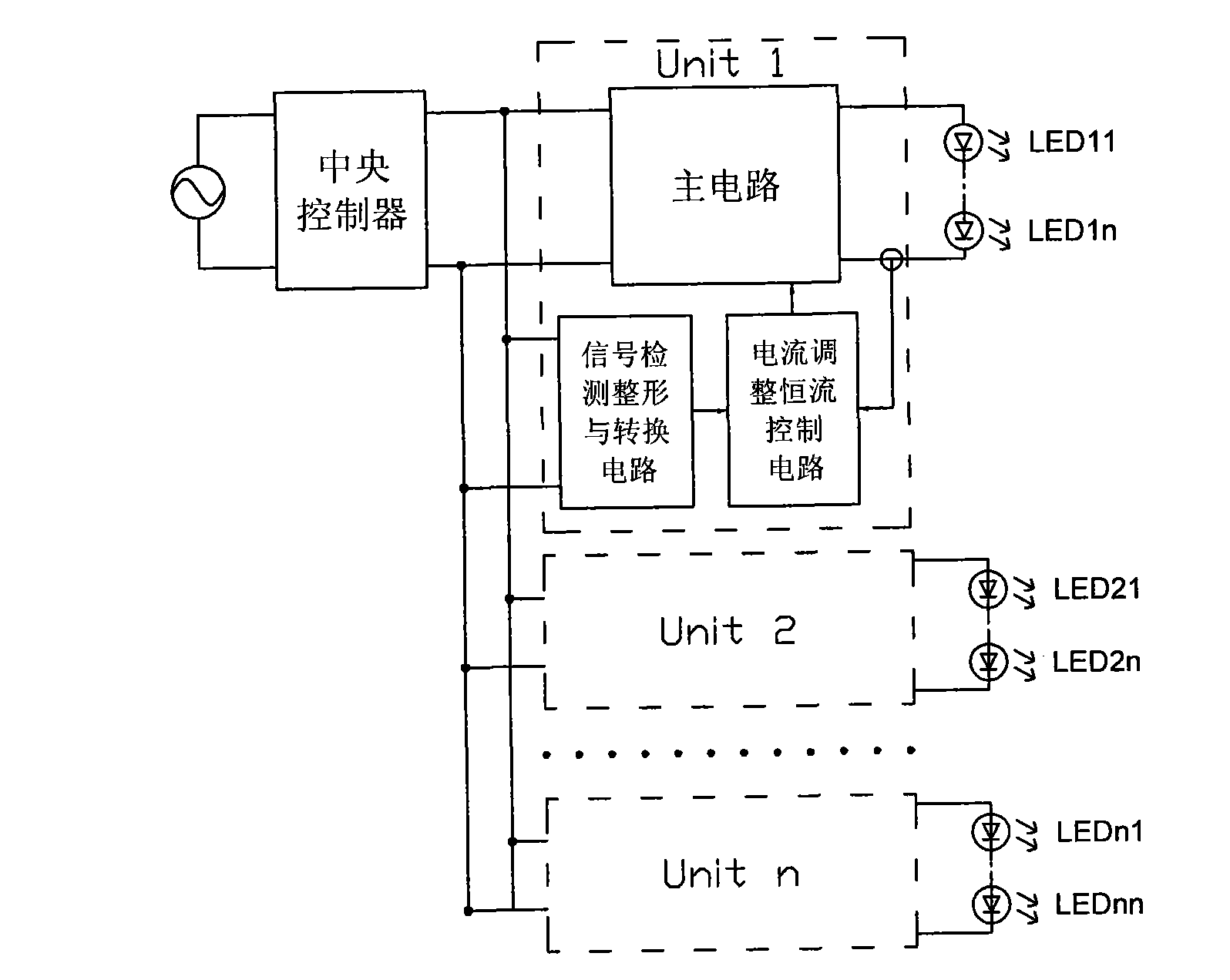
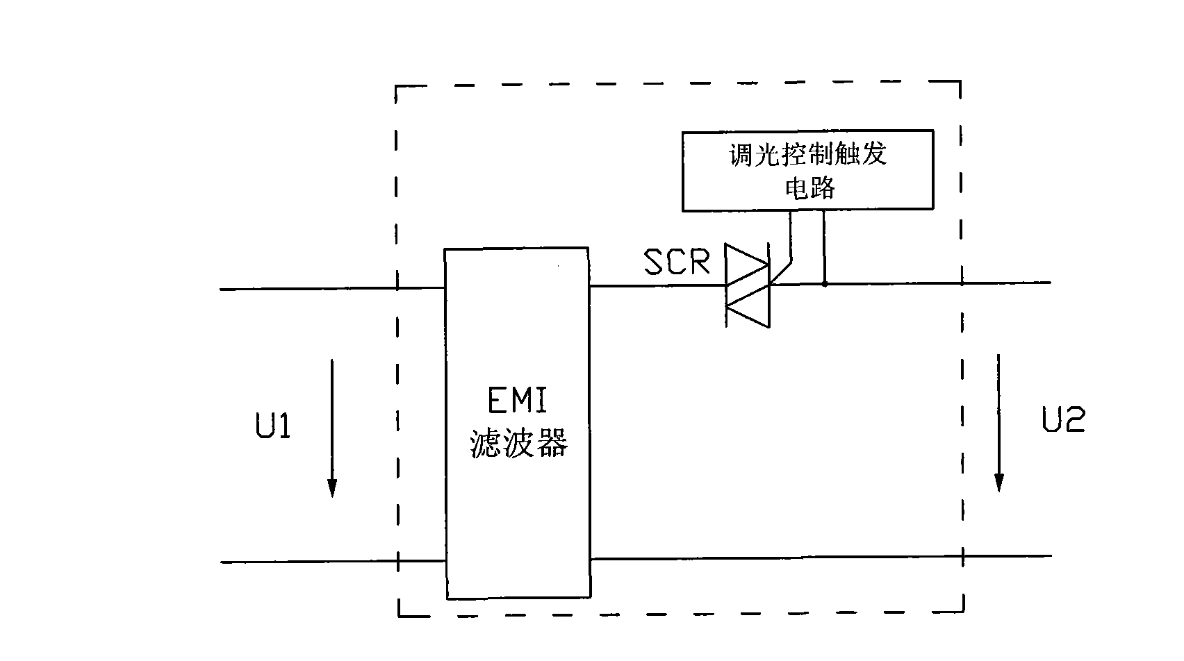
[0027] refer to Figure 2-4 The centralized dimming circuit of the LED lighting system of the present invention includes a central controller and a multi-channel LED drive circuit, the central controller includes an EMI filter, a bidirectional control thyristor SCR and a dimming control trigger circuit, and the The thyristor SCR triggers the conduction phase angle by adjusting the dimming control trigger circuit, and sends out a dimming control signal; the dimming control trigger circuit includes a manual brightness adjustment trigger circuit, and / or an ambient brightness detection and brightness adjustment trigger circuit, and / or timing control and adjustment trigger circuit, outputting manual, light control and / or time control dimming signals;

[0028] Each LED drive circuit includes a main circuit, a signal detection shaping and conversion circuit, a current adjustment and constant current control circuit, the main circuit accepts the control of the current adjustment and ...


PUM


Abstract

The invention discloses a centralized light modulation circuit in LED illumination system, which comprises a central controller and a multipath LED drive circuit; The central controller comprises a thyristor SCR and a light modulation control trigger circuit; the light modulation control trigger circuit comprises a hand-operated brightness adjusting trigger circuit, and / or a ambient brightness detecting and brightness adjusting trigger circuit, and / or a timing control adjusting trigger circuit, and outputs hand-operated and / or time controlled light modulation signals; and each LED drive circuit comprises a main circuit, a signal detection shaping and converting circuit, a current adjusting and constant current controlling circuit. In the invention, the small-ranged variation of conduction angle of controlled silicon in the central controller can obtain wide range light modulation effect; and the invention has simple circuit and low cost, generate no great harmonic wave, and reduces harmonic wave pollution.

Description

technical field [0001] The invention relates to a dimming circuit of an LED lighting system. Specifically, it should be a centralized control circuit capable of realizing the brightness of multiple LED lighting systems. Background technique [0002] With the increasing energy consumption, the requirements for energy saving are also getting higher and higher, and lighting electricity consumption is an important part of people's energy consumption. As an energy-saving and green lighting method, new LED lighting will replace traditional gas discharge lamps and incandescent lamps. LED has long service life, high luminous efficiency, and can save a lot of electric energy, and the driving and control method of LED is simple, which is convenient for flexible adjustment of luminous brightness, especially suitable for some applications where luminous brightness needs to be adjusted according to different situations, such as street lamps, squares, etc. Public places and indoor light...

Claims


Application Information

Patent Timeline
IPC IPC(8): H05B37/02
Inventor 华桂潮吴新科姜德来罗长春杨永兵
Owner INVENTRONICS HANGZHOU
Features
  • R&D
  • Intellectual Property
  • Life Sciences
  • Materials
  • Tech Scout
  • Unparalleled Data Quality
  • Higher Quality Content
  • 60% Fewer Hallucinations
Learn More