Sick bed driving device of magnetic resonance system

A driving device and magnetic resonance technology, applied in the fields of medical science, diagnosis, diagnosis recording/measurement, etc., can solve the problems of increasing the workload of scanning operators, occupying a large space, and being insufficient for scanning inspections.

Active Publication Date: 2009-08-05
SIEMENS HEALTHINEERS LTD
View PDF1 Cites 12 Cited by
  • Summary
  • Abstract
  • Description
  • Claims
  • Application Information

AI Technical Summary

Problems solved by technology

However, this split-type hospital bed device needs to occupy a large space, and since the hospital bed device and the magnet of the magnetic resonance system are not integrated, the requirements for the installation site of the magnetic resonance system are very high, and the requirements for the magnetic resonance system are significantly increased. The workload of the coordination and debugging of the split hospital bed device and the magnetic resonance system
[0004] This split bed device can manually move the bed in one-dimensional (longitudinal) or two-dimensional (vertical and longitudinal) directions, but this increases the workload of scanning operators
Optionally, a power mechanism can also be set on the side of the hospital bed device, and the motor drives the bed to move, but since the motor is also located on the side of the magnet of the magnetic resonance system and moves with the movement of the bed, this will affect the magnetic field of the magnet The shimming parameters will further affect the imaging quality of the image
[0005] The other is a hospital bed device that is installed on the column of the magnet of the magnetic resonance system and is integrated with the magnet. However, the current integrated hospital bed device is similar to the above-mentioned split type hospital bed device, and most of the hospital beds can only be realized in one dimension ( Longitudinal) or two-dimensional (vertical and longitudinal) movement, very few can achieve three-dimensional (vertical, longitudinal, transverse) movement, but due to the limitation of the power mechanism, the movement range in the transverse direction is very small, insufficient To meet the needs of scanning inspection; at the same time, since the motor is arranged on both sides of the magnet, it will also affect the shimming parameters of the magnetic field as mentioned above, and then affect the imaging quality of the image

Method used


Image

  • Sick bed driving device of magnetic resonance system
  • Sick bed driving device of magnetic resonance system
  • Sick bed driving device of magnetic resonance system

Examples


Embodiment Construction

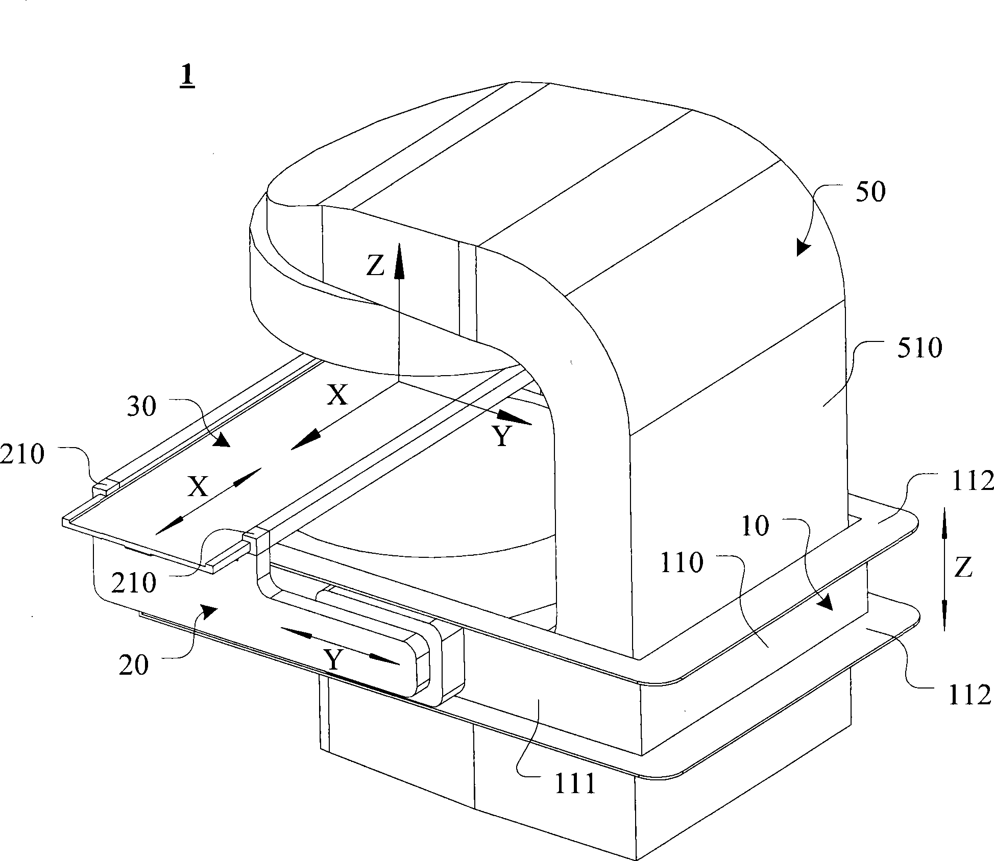
[0040] The following description takes the bed drive device of the magnetic resonance system of the present invention as an example for illustration in a C-shaped open magnetic resonance system, but it can be understood that the present invention can also be applied to other magnetic resonance systems without Limited to open MRI systems.

[0041] see figure 1 , the magnetic resonance system 1 includes a C-shaped magnet 50 , and the magnet 50 includes a column portion 510 . The bed driving device of the magnetic resonance system of the present invention includes a bracket 10 , arms 20 on both sides and a bed 30 that cooperate with each other.

[0042] For the convenience of description, a three-dimensional Cartesian coordinate system is specially defined, which takes the left-right direction of the magnetic resonance system 1 (the direction passing through the opening of the C-shaped magnet 50) as the X-axis, and the X-axis corresponds to the longitudinal direction of the move...


PUM


Abstract

The invention provides a hospital bed driving device for a magnetic resonance system. The magnetic resonance comprises a magnet of which the front has an upright post part, and the hospital bed driving device comprises a bracket, side arms and a hospital bed, the bracket comprises bottom edges and two side edges, and can be movably arranged on the upright post part of the magnet and drive the bracket to move up and down through a motor; the side arms can be movably arranged on two sides of the bracket and are driven to move left and right through a motor; and the hospital bed is arranged in the side arms and is driven by a motor to move left and right. Through the up-and-down, front-and-back and left-and-right movements of the bracket, the side arms and the hospital bed, the three-dimension drive of the bed is realized. At the same time, the motors driving the bracket, the side arms and the hospital bed are all arranged on the rear surface of the magnetic and do not move with the hospital bed, thereby avoiding influence on the shimming parameters of the magnet and on the imaging quality of the image of magnetic resonance equipment.

Description

technical field [0001] The present invention relates to a magnetic resonance system, in particular to a bed driving device for a magnetic resonance system Background technique [0002] There are generally two types of bed devices used in conjunction with scanning examinations for magnetic resonance systems on the market, especially permanent magnetic resonance systems. [0003] One is a split bed unit, where a separate bed unit is placed next to the MRI system for operation. However, this split-type hospital bed device needs to occupy a large space, and since the hospital bed device and the magnet of the magnetic resonance system are not integrated, the requirements for the installation site of the magnetic resonance system are very high, and the requirements for the magnetic resonance system are significantly increased. The workload of the coordination and debugging of the split hospital bed device and the magnetic resonance system. [0004] This split bed device can manu...

Claims


Application Information

Patent Timeline
Patent Type & Authority Applications(China)
IPC IPC(8): A61B5/055
Inventor 薛廷强裴建华
Owner SIEMENS HEALTHINEERS LTD
Why Eureka
Try Eureka