Method for messaging in routing non-access layer

A non-access layer message and message technology, applied in access restriction, electrical components, wireless communication, etc., to reduce the impact

Inactive Publication Date: 2009-08-05
HUAWEI TECH CO LTD
0 Cites 44 Cited by

AI-Extracted Technical Summary

Problems solved by technology

[0011] The purpose of the embodiments of the present invention is to provide a method for routing non-access layer messages, so as to solve how to reduce the interface connection betwe...

Abstract

The invention discloses a method for routing a non access stratum (NAS) message, comprising the following steps: user equipment (UE) sends a first NAS message to an access network node; a core network node is selected according to incidence relation information, and the selected core network node is taken as a second core network node which is provided with interface configuration with a home base station (HNB) associated with the UE; and the first NAS message is sent to the second core network node. The invention provides the UE, the access network node and the core network node. The use of the method can reduce the interface connection between the access network node and the core network node, and reduce the influence on network functions such as user mobility and the like.

Application Domain

Technology Topic

Home basedAccess network +3

Image

  • Method for messaging in routing non-access layer
  • Method for messaging in routing non-access layer
  • Method for messaging in routing non-access layer

Examples

  • Experimental program(1)

Example Embodiment

[0027] In order to make the objectives, technical solutions, and beneficial effects of the embodiments of the invention clearer, the specific implementations of the embodiments of the invention will be described in detail below with reference to the accompanying drawings.
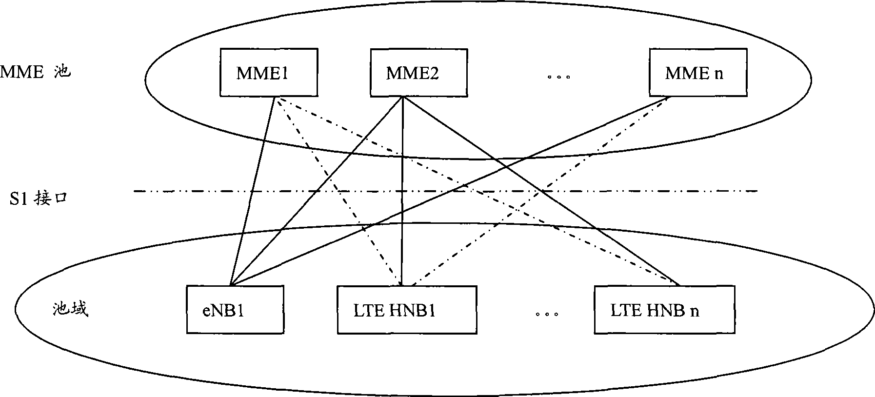
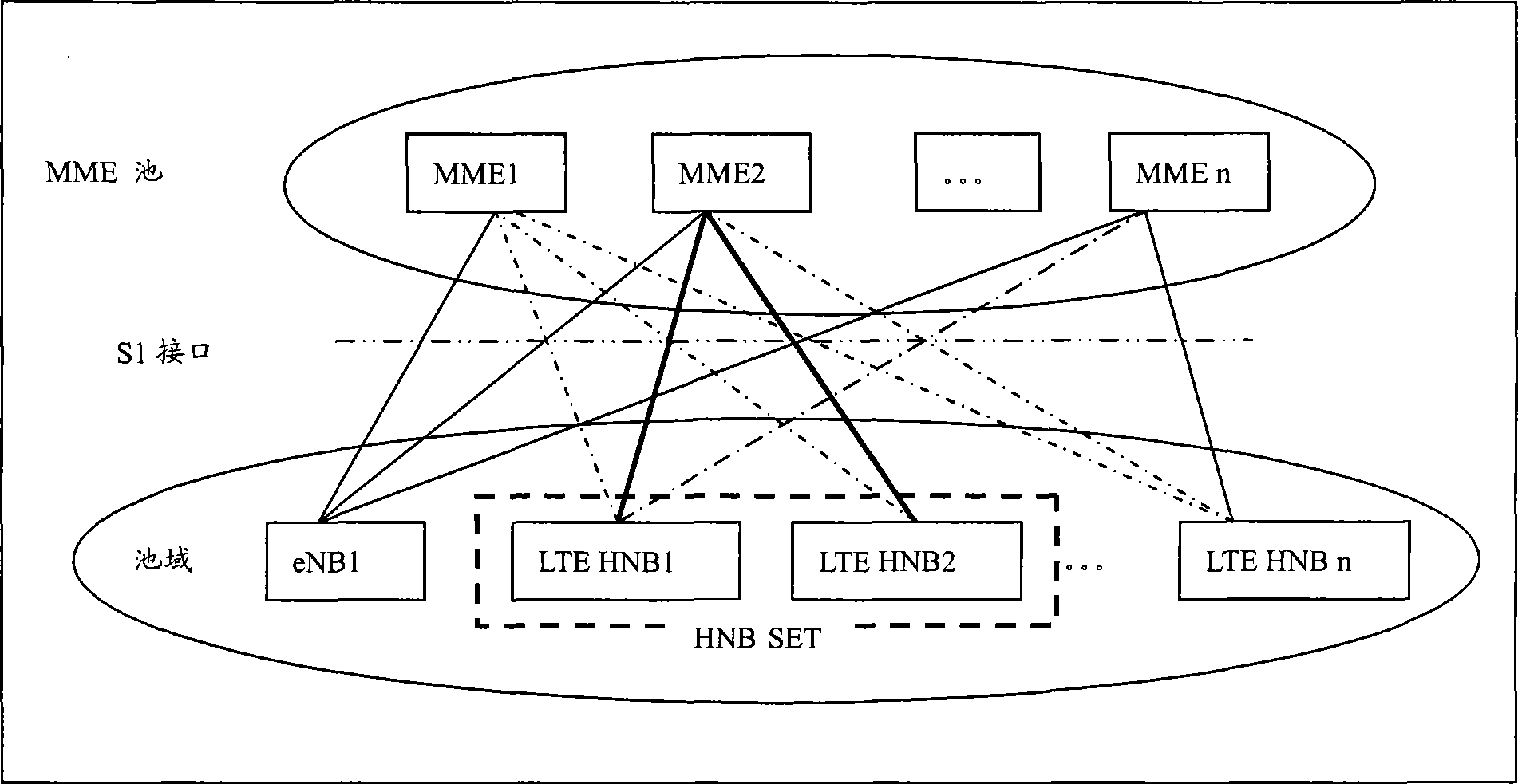
[0028] In the embodiment of the present invention, the access network node and the core network node may be the eNB and the MME in the SAE/LTE system, respectively. At this time, the interface between the eNB and the MME is the S1 interface, or the RNC and SGSN in the UMTS system. At this time, the interface between RNC and SGSN is the Iu interface. In the embodiment of the present invention, an SAE/LTE system is taken as an example for description. The interface configuration relationship mentioned below refers to the interface configuration between the UE and the HNB and/or between the HNB and the core network node.
[0029] The embodiment of the present invention first proposes a method suitable for setting the interface configuration relationship. A UE can use one or more private LTE HNBs. We call the set of these LTE HNBs that have a use relationship with a certain UE as the UE's LTE HNB set (or HNB SET for short). The LTE HNBs belonging to the same HNB SET have the same S1 interface connection configuration, that is, they are connected to the same MME. Such as figure 2 As shown, if both LTE HNB1 and LTE HNB2 can be used by a certain UE, then LTE HNB1 and LTE HNB2 belong to the HNB SET of the UE, and both are connected to MME2.
[0030]If a UE belongs to both a home LTE HNB and an office LTE HNB, the home LTE HNB and the office LTE HNB can be designed as different HNB SETs, that is, the HNB in ​​the HNB SET can only be A part of all HNBs that the UE has an association relationship. When the UE moves from the home to the office, the possible relocation between MMEs will not cause much impact. However, if these two HNB SETs are to be merged and connected to the same or multiple MMEs, it may cause the introduction of multiple different HNB SETs that cross each other, causing a significant increase in the number of S1 interfaces from the HNB SET to the MME.
[0031] Of course, in addition to the two interface configuration methods suggested in the embodiments of the present invention described above, technicians can also perform interface configuration according to other methods according to actual needs, such as according to the load situation of core network nodes.
[0032] The following describes an embodiment of an embodiment using the above-mentioned interface configuration relationship to achieve the purpose of the invention.
[0033] MME sends the interface configuration relationship between LTE HNB and MME to UE through NAS message. This process can use attach process, or location area update (Locating Area Updating, LAU), tracking area update (Tracking Area Updating, TAU) and other processes . In this embodiment, the attach process is used to send, such as image 3 Shown is a schematic flowchart of an embodiment of the present invention:
[0034] Step 301: The UE sends an RRC message to the eNB, which carries an attach request NAS message;
[0035] Step 302: The eNB selects an MME according to algorithms such as NNSF or load balancing, and the selected MME is MME1;
[0036] In step 302, the NNSF is a NAS node selection function, but at this time, the MME1 selected by the eNB is probably not an MME that has an interface configuration relationship with the HNB associated with the UE.
[0037] Step 303: The eNB sends an S1-AP message to MME1, which carries an attach request NAS message;
[0038] Step 304: MME1 queries the interface configuration relationship and determines whether there is an HNB SET associated with the UE. If not, execute the existing procedure; if so, determine whether the HNB SET associated with the UE has an interface configuration relationship. If yes, perform the existing steps according to the existing procedure; if not, the MME1 sends an S1-AP message to the eNB, the message carries an attach rejection NAS message, and the NAS message contains association information;
[0039] The association relationship information in step 304 refers to an interface configuration relationship or a list of interface configuration relationships;
[0040] The interface configuration relationship can be stored in MME1 or in a certain network server in the network, such as entities such as HLR and HSS.
[0041] Step 305: The eNB sends an RRC message to the UE, which carries the above-mentioned attach rejection NAS message;
[0042] Step 306: The UE parses the RRC message, obtains and saves the above-mentioned association relationship information, and sends an RRC message to the eNB, which carries the attach request NAS message and the above-mentioned association relationship information;
[0043] Step 307: the eNB parses out and saves the association relationship information from the RRC message, and selects an MME according to the association relationship information, the selected MME is MME2, and the MME2 has an interface configuration relationship with the HNB SET associated with the UE;
[0044] Step 308: The eNB sends an S1-AP message to MME2, and the message carries an attach request NAS message;
[0045] Step 309: MME2 sends an S1-AP message to the eNB, which carries the attach accept NAS message and the TMSI allocated by MME2 for the UE;
[0046] Step 310: The eNB sends an RRC message to the UE, which carries the attach accept NAS message and the TMSI allocated by the MME2 to the UE.
[0047] In this embodiment, if MME1 sends a list of interface configuration relationships, that is, there are multiple interface configuration relationships, the eNB may also select one MME2 in the list based on historical records or algorithms such as load balancing. Through the method of this embodiment, it is ensured that the UE will not perform MME relocation when switching between the current eNB and the HNB in ​​the HNB SET that has an interface configuration relationship with the selected MME2. And after the UE obtains the TMSI allocated by MME2, the next time the UE sends a NAS message, the eNB can correctly route the NAS message to MME2 according to the TMSI.
[0048] The following describes another embodiment of the embodiment that uses the above-mentioned interface configuration relationship to achieve the purpose of the invention.
[0049] The MME sends an identification ID to the UE through a NAS message, and this process can use an attach process or a TAU process. In this embodiment, the attach process is used to send. Such as Figure 4 Shown is a schematic flowchart of another embodiment of the present invention:
[0050] Step 401 to step 403 are the same as step 301 to step 303;
[0051] Step 404: MME1 queries the interface configuration relationship and determines whether there is an HNB SET associated with the UE. If not, execute the existing procedure; if so, determine whether the HNB SET associated with the UE has an interface configuration relationship. If yes, perform the existing steps according to the existing procedure; if not, then MME1 selects an MME that has an interface configuration relationship with the HNB SET associated with the UE, the selected MME is MME2, and sends an attach reject NAS message to the UE, The NAS message carries association relationship information, and the association relationship information is an identifier related to MME2;
[0052] In step 404, the identifier related to MME2, the identifier may be the identifier of MME2, the MME identifier generally includes MME pool ID (MME pool ID), MME ID, etc.; it may also carry an interface configuration relationship with MME2 and associated with the aforementioned UE The CSG ID of the closed user group to which the LTE HNB belongs in the HNB SET may also be an identification list of HNBs that have an interface configuration relationship with MME2 and are associated with the aforementioned UE, that is, the HNB list ID;
[0053] Step 405: The eNB sends an RRC message to the UE, which carries the NAS message containing the above attachment rejection;
[0054] Step 406: The UE parses the RRC message, obtains and saves the above-mentioned identifier related to MME2, and sends an RRC message to the eNB, which carries the attach request NAS message and the above-mentioned identifier related to MME2;
[0055] Step 407: the eNB parses the above RRC message, obtains the above identifier related to MME2, and selects MME2 according to the identifier;
[0056] In this step, the eNB can save the identity, and if the identity carried in the NAS message is the MME2 identity, the eNB can directly select the MME2. If the identity is the CSG ID or the HNB list ID, the eNB will use the association information, that is, the above-mentioned identity and save Query the interface configuration relationship between the LTE HNB and MME and select the information of MME2.
[0057] Step 408: The eNB sends an S1-AP message to MME2, and the message carries an attach request NAS message;
[0058] Step 409-Step 410 are the same as Step 309-Step 310.
[0059] In this embodiment, if the eNB obtains a list of interface configuration relationships by querying, that is, there are multiple interface configuration relationships, the eNB may also select one MME2 in the list based on historical records or algorithms such as load balancing. Through the method of this embodiment, it is guaranteed that the UE will not perform MME relocation when switching between the current eNB and the HNB in ​​the HNB SET in the interface configuration relationship (or list).
[0060] The above two embodiments describe the method of using the interface configuration relationship to select the MME during the UE attachment process. The method can also be the LTE HNB associated with the UE through a certain network server configuration and which MMEs When the S1 interface is connected, or after the configuration connection is completed, the network server informs the MME that has an interface configuration relationship with the LTE HNB, and sends a message to notify the UE of the association relationship information, that is, the interface configuration relationship. The message can be a paging message or an SMS message Or other notification messages. It may also be that the network server informs the UE of the interface configuration relationship through a certain method without going through the MME. Through this method, when the UE is in the attach process or TAU, RAU and other processes, the UE can select the appropriate MME according to the association relationship information, and when sending the related NAS message to the eNB, it also carries the above-mentioned MME identifier, then the eNB The NAS message can be routed to the MME directly according to the identifier.
[0061] The following describes another embodiment of the embodiment that uses the above-mentioned interface configuration relationship to achieve the purpose of the invention.
[0062] When the UE initially performs the attach process or the TAU process, when the eNB selects an MME to route NAS messages according to algorithms such as NNSF or load balancing, it is likely that the MME selected by the eNB at this time does not have an interface configuration relationship with the HNB SET associated with the UE. MME. Then the MME obtains the interface configuration relationship among the UE, HNB, and MME by querying, selects an MME with an interface configuration relationship in the HNB SET associated with the UE, and relocates to the newly selected MME, such as Figure 5 Shown is a schematic flowchart of another embodiment of the present invention:
[0063] Step 501 to step 503 are the same as step 301 to step 303;
[0064] Step 504: MME1 queries the interface configuration relationship and determines whether there is an HNB SET associated with the UE. If not, execute the existing process; if so, determine whether the HNB SET associated with the UE has an interface configuration relationship. If yes, perform the existing steps according to the existing process; if not, MME1 selects an MME with an interface configuration relationship for the HNB SET associated with the UE according to the association relationship information, that is, the above interface configuration relationship, and the selected MME is MME2 ;
[0065] Step 505: MME1 sends a relocation request message to MME2, which carries the identifier of the eNB and the attachment request NAS message;
[0066] Step 506: MME2 sends a relocation response message to MME1;
[0067] Step 507: MME2 sends an S1-AP message to the aforementioned eNB, the message carrying an attach accept NAS message, the IMSI of the UE, and the TMSI allocated by the MME2 for the UE;
[0068] Step 508: The eNB sends an RRC message to the UE according to the above IMSI, and the message carries an attach accept NAS message and the TMSI allocated by MME2.
[0069]In this embodiment, MME1 may also send related information of MME2 to UE, such as Figure 6 Shown is a schematic flow diagram of the method, and the flow includes:
[0070] Step 601-Step 604 are the same as Step 501-Step 504;
[0071] Step 605: MME1 sends a relocation request message to MME2;
[0072] Step 606: MME2 sends a relocation response message to MME1, which carries the TMSI allocated by MME2 for the UE;
[0073] Step 607: MME1 sends an S1-AP message to the above-mentioned eNB, and the message carries an attach accept NAS message and the TMSI allocated by MME2 for the UE;
[0074] Step 608: The eNB sends an RRC message to the UE, which carries the attach accept NAS message and the TMSI allocated by the MME2.
[0075] In this embodiment, the MME1 that the UE tries to access for the first time obtains the interface configuration relationship (list) with the UE, HNB, and MME through query, and finds that it is not the MME that has an interface configuration relationship with the associated HNBSET of the UE. And select a new MME2 according to the interface configuration relationship, and send a relocation message to the MME2 to attach to the UE. This ensures that the UE can perform between the current eNB and the HNB in ​​the HNB SET in the interface configuration relationship (or list). During handover, no MME relocation will be performed. And after the UE obtains the TMSI allocated by MME2, the next time the UE sends a NAS message, the eNB can route the NAS message to MME2 according to the TMSI.
[0076] The following describes another embodiment of the embodiment that uses the above-mentioned interface configuration relationship to achieve the purpose of the invention.
[0077] Another embodiment of the present invention is to segment the IMSI numbers allocated by the operator to the UE, for example, 400 IMSIs are divided into one interval, and this interval corresponds to one MME.
[0078] Then, when the network server configures the S1 interface for the LTE HNB, it first checks which UEs the LTE HNB can serve. For example, the LTE HNB can be used by four UEs (UE1, UE2, UE3, UE4). These four UEs correspond to four IMSIs, which can be determined to be related to a certain MME according to the interval to which the UE's IMSI belongs. If the IMSIs of the above four UEs belong to the same IMSI segment, then during configuration, an S1 interface is established between the LTE HNB and the MME corresponding to the IMSI segment. If the above four IMSIs belong to four different IMSI intervals, then the LTE HNB needs to establish S1 interfaces with different MMEs corresponding to the different IMSI intervals. Such as Figure 7 Shown is a schematic flowchart of another embodiment of the present invention, and the process includes:
[0079] Step 701: The UE sends an attach request NAS message to the eNB, and the NAS message is carried in an RRC message and sent;
[0080] Step 702: the eNB selects the MME according to the IMSI of the UE and the stored association relationship information;
[0081] In the above steps, the eNB judges that the UE is associated with a certain LTE HNB according to the IMSI of the UE, and then selects the MME according to the IMSI and the association relationship information saved by the eNB, that is, the interface configuration relationship between the HNB and the MME. The foregoing method performs the configuration of the S1 interface between the LTE HNB and the MME, and the MME selected by the eNB according to the IMSI of the UE must have an S1 interface configuration relationship with the LTE HNB associated with the UE;
[0082] Step 703: The eNB sends an S1-AP message to the MME, and the message carries an attach request NAS message;
[0083] Step 704: The MME sends an S1-AP message to the eNB, which carries the attach accept NAS message and the TMSI allocated by the MME for the UE;
[0084] Step 705: the eNB sends an RRC message to the UE, which carries the attach accept NAS message and the TMSI allocated by the MME to the UE.
[0085] Using the method of this embodiment can reduce the connection between the LTE HNB and the MME.
[0086] The solution of the above embodiment is also applicable to the UMTS system. In the UMTS system, the interface configuration relationship among the UE, 3G HNB SET, and SGSN is used for SGSN selection, that is, the UE selects the 3G HNB SET associated with the UE. SGSNs with an interface configuration relationship are attached, so when the UE switches between the current NodeB and the 3G HNB in ​​the 3G HNB SET, there is no need to perform SGSN relocation.
[0087] The embodiment of the present invention also provides a user equipment, which includes a transceiver module, a storage module, and a selection module, wherein:
[0088] The transceiver module 801 is used to send RRC messages carrying NAS messages to access network nodes, and is also used to receive RRC messages carrying NAS messages sent by access network nodes, and is also used to receive RRC messages carrying TMSI sent by access network nodes. Message, the aforementioned RRC message may also carry association relationship information, and is also used to receive notification messages carrying association relationship information;
[0089] The storage module 802 is used to store association relationship information;
[0090] The selection module 803 is configured to select, according to the association relationship information, a core network node with an interface configuration relationship for the HNB SET associated with the UE.
[0091] The embodiment of the present invention also provides an access network node for routing NAS messages. The node includes a transceiver module, a storage module, and a selection module.
[0092] The transceiver module 901 is configured to receive RRC messages carrying NAS messages sent by the UE, and also used to send S1-AP messages carrying NAS messages to the first core network node or the second core network node, and also used to send from the first core network The node or the second core network node receives the S1-AP message carrying the NAS message, the S1-AP message received from the first core network node may also carry association information, and the S1-AP message received from the second core network node may also carry TMSI allocated by the second core network node to the UE;
[0093] The storage module 902 is used to store association relationship information;
[0094] The selection module 903 is configured to select, according to the association relationship information, a second core network node with an interface configuration relationship for the HNB SET associated with the UE.
[0095] The aforementioned access network node may be an eNB or an RNC.
[0096] The embodiment of the present invention also provides a core network node for routing NAS messages. The node includes a transceiver module, a storage module, and a query module, wherein:
[0097] The transceiver module 1001 is configured to send an S1-AP message carrying association relationship information to an access network node, and is configured to send a relocation request message to a second core network node that has association relationship information in the HNB SET associated with the UE. The location request message may carry the identifier of the aforementioned access network node, and a relocation response message is received from the second core network node, and the relocation response message may carry the TMSI allocated by the second core network node for the UE;
[0098] The storage module 1002 is used for storing association relationship information;
[0099] The query module 1003 is used to query the association relationship information and select the second core network node.
[0100] The aforementioned core network node may be an MME or an SGSN.
[0101] The above is a detailed introduction to a method for routing non-access stratum messages provided by embodiments of the present invention. Specific examples are used in this article to explain the principles and implementation manners of the embodiments of the present invention. The description of the above embodiments is only for To help understand the methods and core ideas of the embodiments of the present invention; at the same time, for those of ordinary skill in the art, according to the ideas of the embodiments of the present invention, there will be changes in the specific implementation and the scope of application. In summary The content of this specification should not be construed as a limitation to the embodiments of the present invention.

PUM

no PUM

Description & Claims & Application Information

We can also present the details of the Description, Claims and Application information to help users get a comprehensive understanding of the technical details of the patent, such as background art, summary of invention, brief description of drawings, description of embodiments, and other original content. On the other hand, users can also determine the specific scope of protection of the technology through the list of claims; as well as understand the changes in the life cycle of the technology with the presentation of the patent timeline. Login to view more.

Similar technology patents

Floating keyboard

InactiveUS20060210340A1Alleviates repetitive stress injuryReduce the impactInput/output for user-computer interactionCathode-ray tube indicatorsAmbulation DevicesEngineering
Owner:ERGOWERX

Combination of sulfonamide compound and tafluprost

InactiveUS20140018350A1Good effectReduce the impactBiocideOintment deliveryTherapy medicationBenzyl group
Owner:SANTEN PHARMA CO LTD +1

Classification and recommendation of technical efficacy words

Why Eureka
Try Eureka