
Exhaust device for engine

A technology for exhaust devices and mufflers, which can be used in exhaust devices, machines/engines, noise reduction devices, etc., and can solve expensive and other problems

Inactive Publication Date: 2009-08-05
TOYOTA JIDOSHA KK
View PDF1 Cites 12 Cited by
  • Summary
  • Abstract
  • Description
  • Claims
  • Application Information

AI Technical Summary

Problems solved by technology

[0005] The first muffler 140 and the second muffler 150 arranged in the transverse direction of the vehicle are relatively expensive if the mufflers 140, 150 have different structures

Method used


Image

  • Exhaust device for engine
  • Exhaust device for engine
  • Exhaust device for engine

Examples


Embodiment Construction

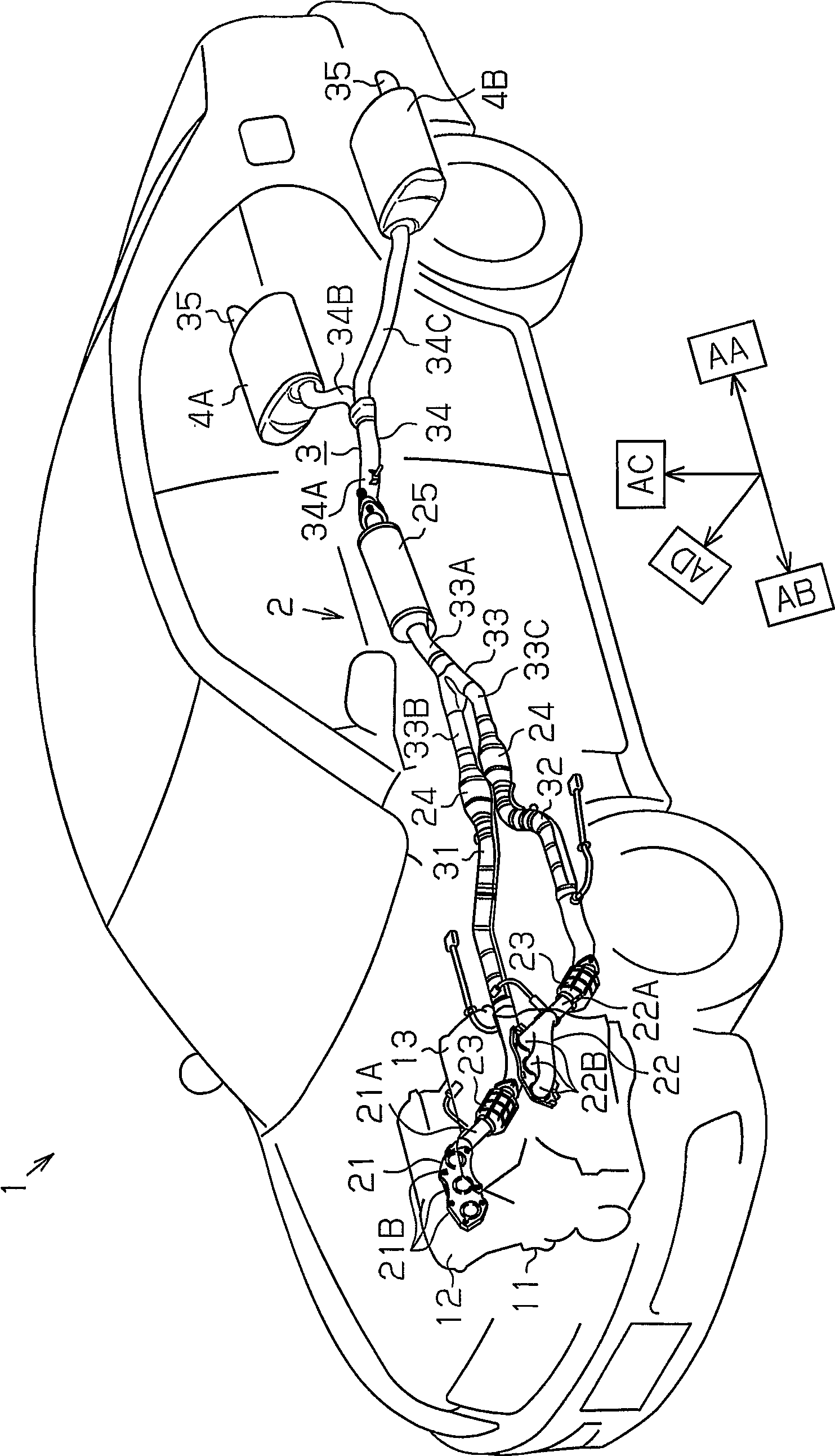
[0067] Figure 1 to Figure 2 9 shows the first embodiment of the present invention.

[0068] figure 1 The exhaust system of the vehicle 1 according to the first embodiment is shown. When defining a given position of the exhaust system as a reference, the side from the reference toward the engine 11 is referred to as the upstream side, and the side from the reference toward the exhaust outlet is referred to as the downstream side. The direction from the upstream side to the downstream side is called exhaust forward AA, and the direction from the downstream side to the upstream side is called exhaust reverse AB. The forward direction AA indicates the direction from the front side of the vehicle 1 to the rear side, and the reverse direction AB indicates the direction from the rear side of the vehicle 1 to the front side. Assume that the height direction AC of the vehicle coincides with the height direction, and that the width direction AD of the vehicle 1 coincides with the h...


PUM


Abstract

A muffling chamber (5) is located between a first main body wall (42A) and a second main body wall (42B) with respect to a height direction (AE). An outflow pipe (8) has: a first opening (8A) that connects an outflow passage (8R) with a muffling chamber (5) in the vicinity of a first main body wall (42A); and a second opening (8C) that connects the outflow passage (8R) with the muffling chamber (5) in the vicinity of a second main body wall (42B). The liquid staying on the first main body wall (42A) of a first muffler (4A) flows into the outflow passage (8R) through the first opening (8A). The liquid staying on a second main body wall (42B) of a second muffler (4B) flows into the outflow passage (8R) through a second opening (8C). Therefore, the symmetry of the first muffler (4A) and the second muffler (4B) is compatible with anti-corrosion.

Description

technical field [0001] The present invention relates to an engine exhaust device including a pair of mufflers arranged in a vehicle transverse direction. Background technique [0002] Figure 36 A typical exhaust is shown. [0003] The V-type engine 100 has a first cylinder bank 101 and a second cylinder bank 102 . An exhaust device 110 is connected to the engine 100 . The exhaust device 110 is provided with: a pair of catalytic converters 120 ; a sub muffler 130 ; a first muffler 140 ; ​​and a second muffler 150 . [0004] Exhaust gas from the first cylinder group 101 passes through the plurality of branch pipes 162 of the first exhaust manifold 160, the main pipe 161, the first front pipe 181, the right catalytic converter 120, the first branch pipe 183B of the first intermediate pipe 183, and the main pipe 183A reaches the secondary muffler 130 . Exhaust gas from the second cylinder group 102 passes through the plurality of branch pipes 172 of the second exhaust manif...

Claims


Application Information

Patent Timeline
IPC IPC(8): F01N1/08F01N1/16F01N13/00F01N13/04F01N99/00
CPCF01N2490/06F01N1/089F01N2290/10F01N2470/04F01N1/163F01N1/16F01N2490/02F01N1/083F01N1/084F01N2470/02F01N2490/08
Inventor 松枝幸治辻朋之
Owner TOYOTA JIDOSHA KK
Features
  • Generate Ideas
  • Intellectual Property
  • Life Sciences
  • Materials
  • Tech Scout
  • Unparalleled Data Quality
  • Higher Quality Content
  • 60% Fewer Hallucinations
Learn More