Vehicle parking apparatus

A technology for parking devices and vehicles, which is applied in the direction of buildings, building types, buildings, etc. where cars are parked. It can solve problems such as difficult road installation, impact on vehicle traffic, and loss of operation, and achieve increased safety and anti-theft performance. The effect of environmental protection and saving, fuel resource saving

Active Publication Date: 2009-08-12
沈嘉琦
View PDF0 Cites 9 Cited by
  • Summary
  • Abstract
  • Description
  • Claims
  • Application Information

AI Technical Summary

Problems solved by technology

However, the existing road parking methods have the following problems: (1) parking occupies the road, which affects the passage of passing vehicles, especially road parking during peak traffic hours is likely to cause congestion or even road congestion; (2) road parking vehicles are easy to The vehicle is damaged due to collision; (3) Since the road is a public area, parking on the road (especially in the off-road section or late at night) has the hidden danger of the vehicle and the property in the car being stolen
However, after the road parking was banned, a certain number of parking spaces were lost, which made the problem of increasingly tight parking spaces and parking difficulties worse.
[0004] In order to alleviate the contradiction of parking difficulties, people have done a lot of efforts in various aspects, and various forms of parking devices and three-dimensional garages have come out one after another. The drop between the platform and the ground, various columns, etc.), it is difficult to directly use the road to install
In addition, the existing parking garage (device) requires a dedicated land area, and its establishment requires land use costs in addition to its own costs, especially in central urban areas where every inch of land is expensive, which easily leads to the dilemma of expensive parking fees and loss-making operations

Method used


Image

  • Vehicle parking apparatus
  • Vehicle parking apparatus
  • Vehicle parking apparatus

Examples


Embodiment Construction

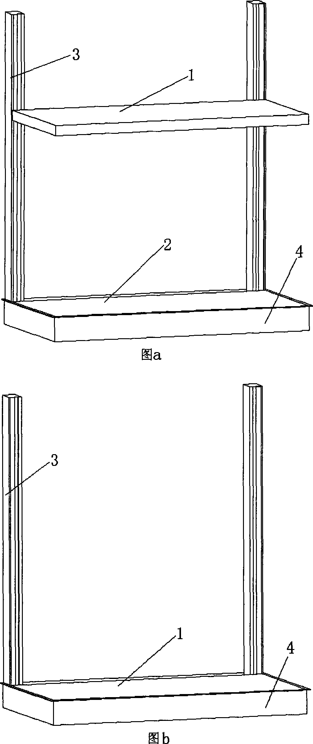
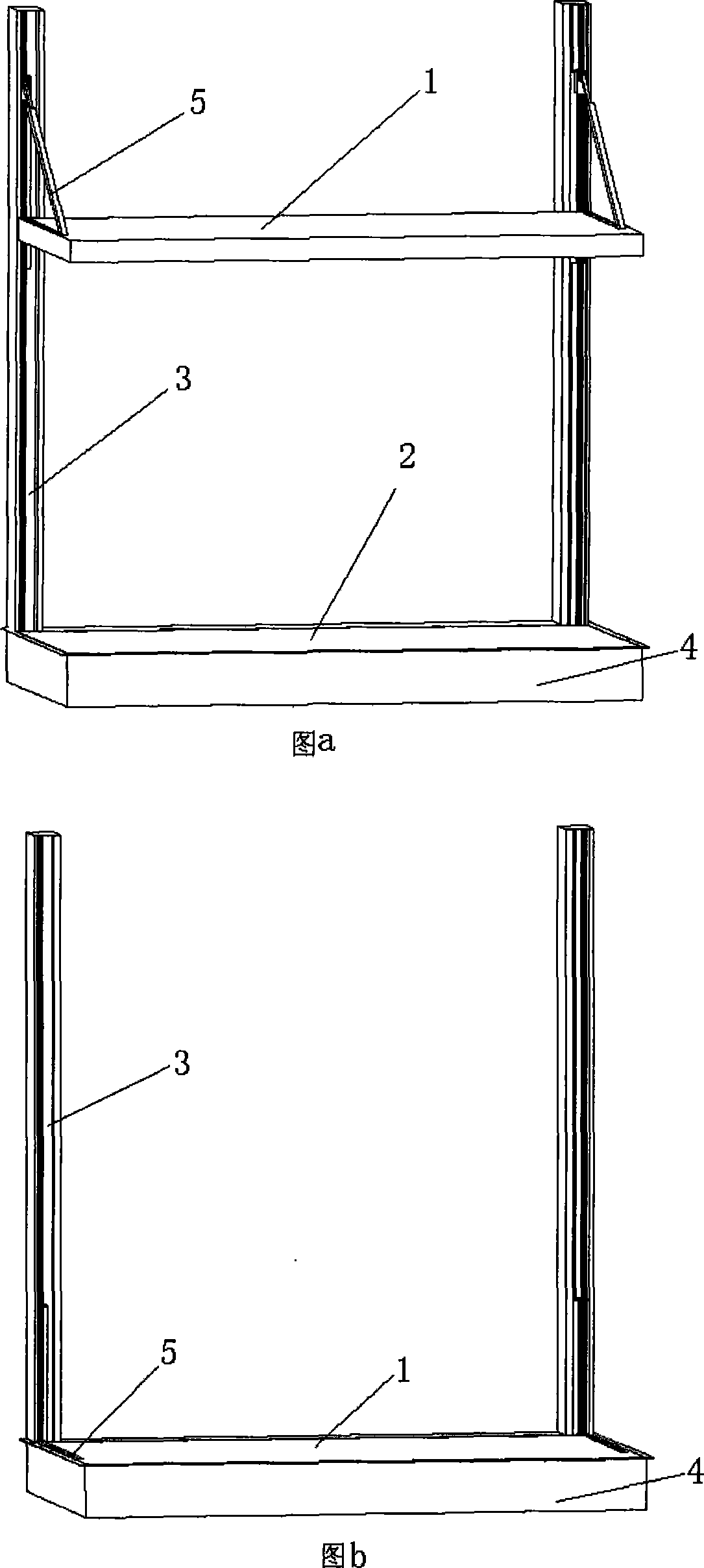
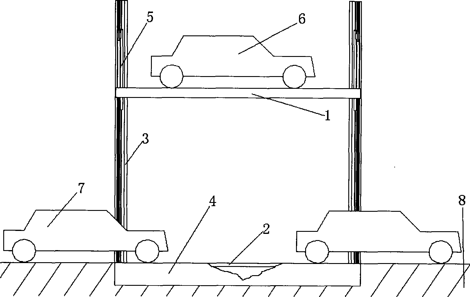
[0018] Parking device provided by the invention (as figure 1 Shown) mainly consists of base (4), column (3), upper platform (1), upper platform lifting mechanism, lower platform (2), lower platform lifting mechanism, control device and each supporting auxiliary parts etc. to form.

[0019] 1. Base(4)

[0020] The base (4) is viewed as a rectangular frame structure from above, and the base (4) is buried in the road surface when the parking device is installed. The outer side of the upper surface of the base frame is connected with the surrounding road surface, and the inner side is connected with the upper platform (1) (when there is no vehicle parking state, if the attached figure 1 Figure b in the attached figure 2 Figure b in the attached Figure 4 shown) or the lower platform (2) (when there are vehicles parked, if attached figure 1 Figure a, attached figure 2 Figure a, attached image 3 shown) fit. The outer road, the upper surface of the base frame and the inner ...


PUM


Abstract

The invention discloses a vehicle parking device, which is a parking device arranged on a vehicle traffic road. The device is provided with an upper-layer platform and a lower-layer platform; the upper layer is a vehicle parking platform; and the lower layer is a road compensation platform. When no vehicle parks, the upper-layer platform is descended to the same height with the ground so as not to influence the vehicle traffic; when the vehicle parks, the upper-layer platform lifts the parked vehicle to the height which does not influence the vehicle traffic; and the lower-layer platform is lifted to the road to fill the road fall remained by the lifting of the upper-layer platform. Therefore, no matter whether the vehicle parks or not, no influence is caused to the driving of the passingvehicles on the road. The vehicle parking device brings convenience to drivers, improves the parking safety of the parked vehicles, and increases the parking lots on the road, thereby releasing the conflict of difficult parking to certain extent and is favorable for environmental protection, energy saving and congestion removal and smoothness maintenance of traffic.

Description

Technical field [0001] The invention relates to a vehicle parking device with a lifting platform. Background technique [0002] When people arrive at their destination by car, parking on the spot on the side of the road is the most desired traditional parking method for drivers. the empty mileage of the vehicle to the parking garage). However, the existing road parking methods have the following problems: (1) parking occupies the road, which affects the passage of passing vehicles, especially road parking during peak traffic hours is likely to cause congestion or even road congestion; (2) road parking vehicles are easy to (3) Since the road is a public area, there is a hidden danger of theft of the vehicle and the property in the car when parking on the road (especially in an off-road section or late at night). [0003] Along with the increase of vehicles, more and more central urban areas, business districts and residential quarters prohibit vehicles from parking on the r...

Claims


Application Information

Patent Timeline
Patent Type & Authority Applications(China)
IPC IPC(8): E04H6/06
Inventor 沈嘉琦沈黎明
Owner 沈嘉琦
Why Eureka
Try Eureka