Mechanical synchronous transmission
A transmission, mechanical technology, applied in mechanical equipment, mechanical control devices, instruments, etc., can solve problems such as reduced engine cruising speed and poor fuel economy
Active Publication Date: 2009-08-12
CHONGQING TSINGSHAN IND
View PDF0 Cites 2 Cited by
- Summary
- Abstract
- Description
- Claims
- Application Information
AI Technical Summary
Problems solved by technology
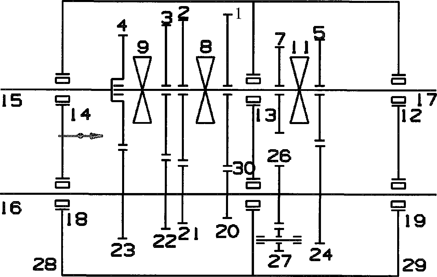
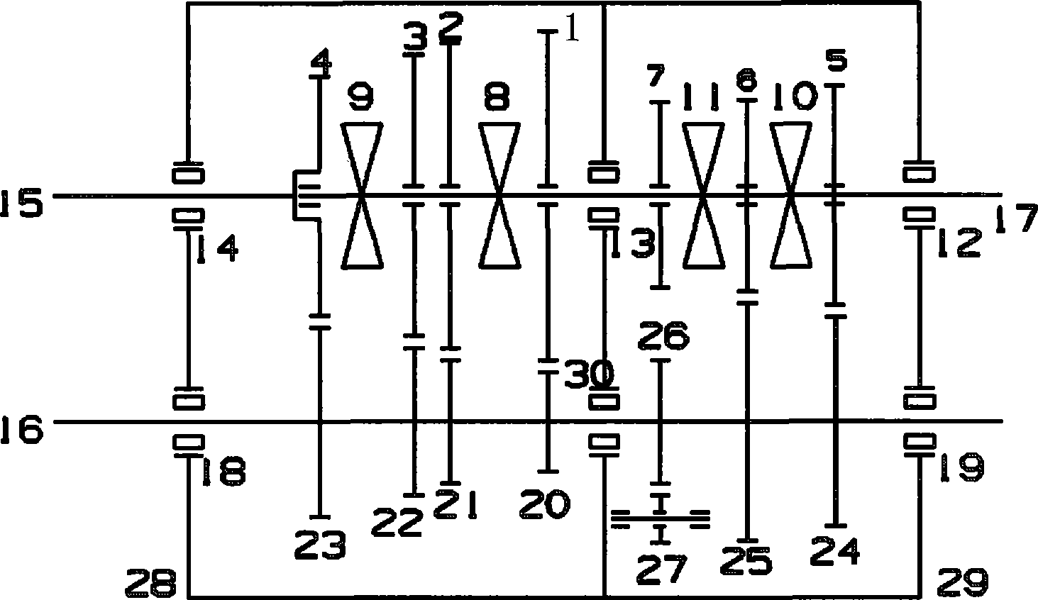
With the implementation of more stringent fuel consumption regulations in the country, it is proposed that the transmission cooperate with the engine and the vehicle to reduce fuel consumption, so that the cruising speed of the engine will be further reduced, and the transmission ratio of the transmission will be wider. +R) gear transmission (such as figure 1 , 2 shown) have the disadvantage of poor fuel economy
Method used
View moreImage
Smart ImageViewing Examples
Examples
Embodiment Construction
[0018] The present invention will be described in further detail below in conjunction with the embodiments and accompanying drawings.
Login to View More PUM
 Abstract
The invention discloses a mechanical synchronous transmission, which mainly comprises a box body, an input shaft, an output shaft, a middle shaft, a gear pair, a synchronizer and a release bearing operating mechanism. The gear pair comprises a first-shift gear pair, a second-shift gear pair, a third-shift gear pair, a fourth-shift gear pair, a fifth-shift gear pair, a reverse gear pair and a box body; and the middle shaft and the output shaft are additionally provided with sixth-shift gear pairs. The mechanical synchronous transmission increases the sixth-shift gears with less transmission ratio; the transmission is matched with an engine to reduce the oil consumption of an integral vehicle so that the integral vehicle achieves the requirements of national discharge and oil consumption; and the mechanical synchronous transmission has reasonable transmission ratio, enough strength and reliability, and higher transmission efficiency and gear shifting comfort, and becomes the development tendency of future manual transmissions.
Description
technical field [0001] The present invention relates to automotive transmissions, specifically mechanical synchronous transmissions. Background technique [0002] The car transmission is a component that changes the engine speed and torque according to the different driving conditions of the car, so that the car has proper traction, acceleration and reverse, while keeping the engine working under the most favorable working conditions. With the implementation of more stringent fuel consumption regulations in the country, it is proposed that the transmission cooperate with the engine and the vehicle to reduce fuel consumption, so that the cruising speed of the engine will be further reduced, and the transmission ratio of the transmission will be wider. +R) gear transmission (such as figure 1 , 2 Shown) all have the disadvantage of poor fuel economy. Contents of the invention [0003] Aiming at the shortcomings of the existing five (5+R) gear transmission, the present inve...
Claims
Login to View More Application Information
Patent Timeline
 IPC IPC(8): F16H3/08F16H3/12F16H63/32
Inventor 吕兵
Owner CHONGQING TSINGSHAN IND
Features
- R&D
- Intellectual Property
- Life Sciences
- Materials
- Tech Scout
- Unparalleled Data Quality
- Higher Quality Content
- 60% Fewer Hallucinations
Learn More Browse by: Latest US Patents, China's latest patents, Technical Efficacy Thesaurus, Application Domain, Technology Topic, Popular Technical Reports.
© 2025 PatSnap. All rights reserved.Legal|Privacy policy|Modern Slavery Act Transparency Statement|Sitemap|About US| Contact US: help@patsnap.com


