Optical position measurement apparatus and method

A technology of measuring device and measuring method, which is applied in the direction of measuring device, optical device, semiconductor/solid-state device testing/measurement, etc.

Active Publication Date: 2009-08-12
SHANGHAI MICRO ELECTRONICS EQUIP (GRP) CO LTD +1
View PDF1 Cites 20 Cited by
  • Summary
  • Abstract
  • Description
  • Claims
  • Application Information

AI Technical Summary

Problems solved by technology

[0003] U.S. Patent No. 6,803,291 discloses a method for keeping the surface layer of the alignment area completely flat after chemical mechanical polishing in the photolithography process, wherein the patent also discloses that there are alignment marks on the semiconductor substrate, but the alignment marks Just a set of grooves with the same structure

Method used


Image

  • Optical position measurement apparatus and method
  • Optical position measurement apparatus and method
  • Optical position measurement apparatus and method

Examples


Embodiment Construction

[0023] In order to better understand the technical content of the present invention, specific embodiments are given together with the attached drawings for description as follows.

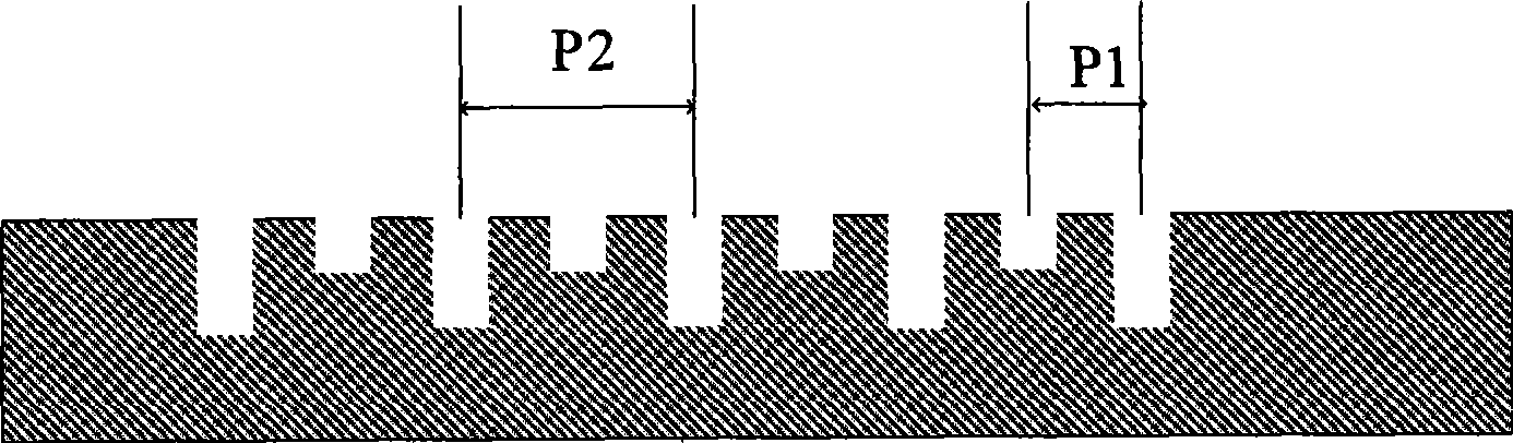
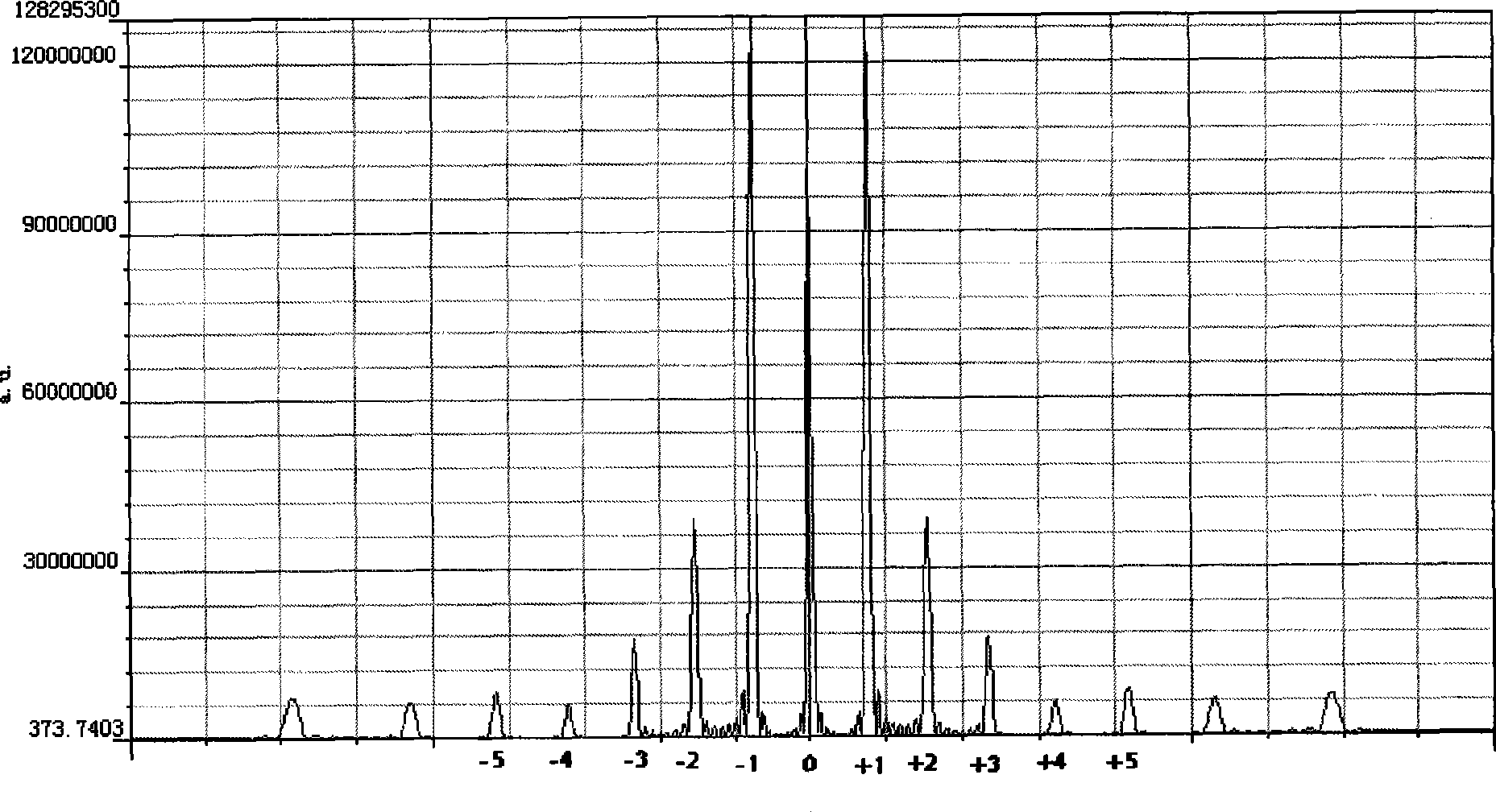
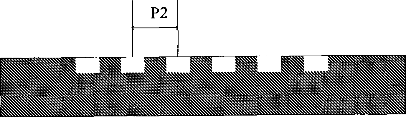
[0024] Figure 1a Shown is a schematic structural diagram of the two-stage enhanced grating used in the optical position measuring device of the present invention. Figure 1b Shown is the simulation diagram of the diffraction energy distribution of the two-stage enhanced grating used in the optical position measuring device of the present invention. Figure 1c Shown is a schematic structural diagram of the two-stage standard grating used in the optical position measuring device of the present invention. Figure 1d Shown is the simulated diagram of the diffraction energy distribution of the 2-stage standard grating used in the optical position measuring device of the present invention. Such as Figure 1a , 1b As shown in , 1c, and 1d, the principle of enhancing the corresponding diffraction order ...


PUM


Abstract

The invention provides a device and a method for measuring the optical position. The method comprises the following steps: adopting a grating diffraction order enhancing method, namely regularly changing the breadth of a grating bar and the depth of a grating slot to obtain a corresponding diffraction order enhanced grating so as to enhance a position measurement signal. The measuring device adopts the grating with two types of cycles as reference marks, namely a first grating and a second grating, uses the light intensity changes modulated by the reference marks after the + / -1 order diffraction light coherent imaging of the first grating and the second grating to obtain large-scale position capture through phase information of a transmitted light signal, simultaneously uses one of the grating to perform enhancement of a corresponding diffraction order, and uses coherent image scanning of the enhanced high diffraction order to perform precise position measurement. Compared with the prior art, the reference marks adopt a grating diffraction order enhancing technique to achieve the position alignment precision, thus the method can support two-dimensional marks and one-dimensional marks.

Description

technical field [0001] The invention relates to a device and method for position measurement and position alignment of a workpiece, in particular to an optical position measurement device and method. Background technique [0002] In the semiconductor manufacturing process, each step requires accurate position positioning. The optical position-measuring device and method to which the present invention pertains are suitable for detecting the position of two objects moving relative to each other in at least one measuring direction. The position measurement device includes a measurement system and a measurement reference mark on the measurement object. The measurement reference mark is composed of different forms of phase gratings, and according to the movement of the measurement object, that is, the movement of the measurement reference mark generates a reference signal for position measurement through the measurement device. Carry out position measurement and position alignme...

Claims


Application Information

Patent Timeline
Patent Type & Authority Applications(China)
IPC IPC(8): H01L21/66H01L21/68G01B11/00
Inventor 杜聚有宋海军徐荣伟韦学志戈亚萍
Owner SHANGHAI MICRO ELECTRONICS EQUIP (GRP) CO LTD
Why Eureka
Try Eureka