Air and air energy recovery ventilation device with bypass defrost function
An energy recovery and ventilation device technology, which is applied in space heating and ventilation, heating and ventilation control systems, heating and ventilation safety systems, etc., can solve the problems of reduced exhaust air volume and reduced heat exchange efficiency, and achieve high efficiency Improve, save energy and manpower, and avoid the effect of heat exchange efficiency decline
- Summary
- Abstract
- Description
- Claims
- Application Information
AI Technical Summary
Problems solved by technology
Method used
Image
Examples
specific Embodiment approach 1
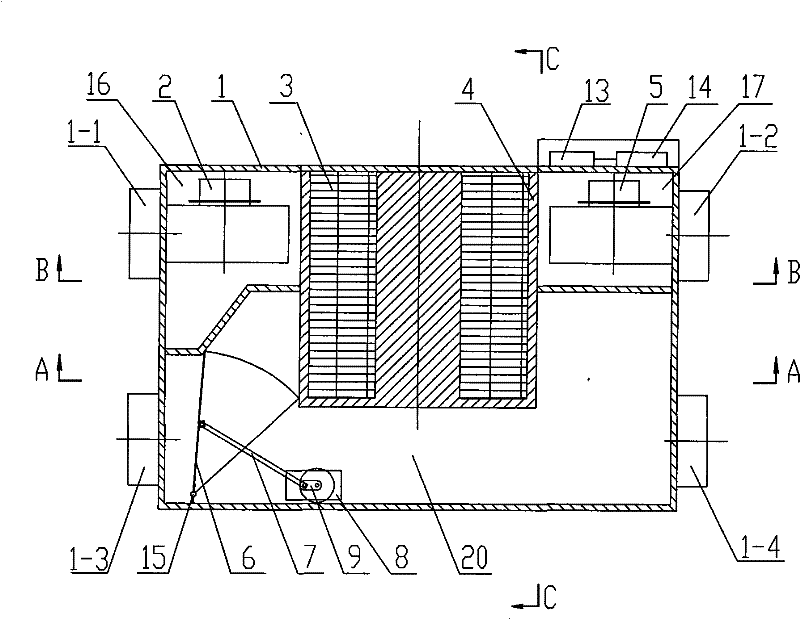
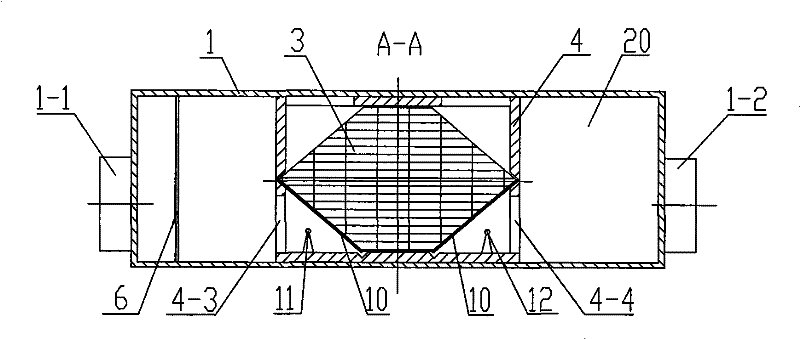
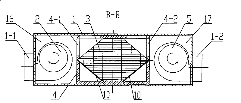
[0007] Specific implementation mode one: combine Figure 1 ~ Figure 4 Describe this embodiment, this embodiment includes casing 1, exhaust fan 2, heat exchanger 3, heat exchanger frame 4, fresh air fan 5, bypass ventilation valve 6, connecting rod 7, motor 8, slider 9, two An air filter 10, a power controller 14 and a hinge 15, the heat exchanger frame 4 is fixedly connected to the top surface, the front inner side wall and the rear inner side wall of the casing 1, and the heat exchanger frame 4 separates the casing 1. It is an exhaust chamber 16, a fresh air chamber 17 and a bypass air passage 20, the heat exchanger 3 is installed in the heat exchanger frame 4, the exhaust fan 2 is installed in the exhaust chamber 16, and the fresh air fan 5 is installed In the fresh air chamber 17, the casing 1 is provided with an exhaust outlet 1-1 at the air outlet of the exhaust fan 2, and the casing 1 is provided with a fresh air outlet 1-2 at the air outlet of the fresh air fan 5. One ...
specific Embodiment approach 2
[0009] Specific implementation mode two: combination figure 1 and figure 2 This embodiment is described. The difference between this embodiment and the first embodiment is that it also adds a fresh air temperature and humidity sensor 11, an exhaust air temperature and humidity sensor 12, and a temperature and humidity acquisition controller 13. The fresh air temperature and humidity sensor 11 is located by the first wind. In the area formed by the channel opening 4-3, the air filter screen 10 adjacent to the first air channel opening 4-3, and the heat exchanger frame 4, and the fresh air temperature and humidity sensor 11 is installed behind the heat exchanger frame 4 On the inner side wall, the exhaust air temperature and humidity sensor 12 is located in the area formed by the second air duct opening 4-4, the air filter 10 adjacent to the second air duct opening 4-4 and the heat exchanger frame 4, And the exhaust air temperature and humidity sensor 12 is installed on the ...
PUM
 Abstract
Description
Claims
Application Information
 - R&D
- Intellectual Property
- Life Sciences
- Materials
- Tech Scout
- Unparalleled Data Quality
- Higher Quality Content
- 60% Fewer Hallucinations
Browse by: Latest US Patents, China's latest patents, Technical Efficacy Thesaurus, Application Domain, Technology Topic, Popular Technical Reports.
© 2025 PatSnap. All rights reserved.Legal|Privacy policy|Modern Slavery Act Transparency Statement|Sitemap|About US| Contact US: help@patsnap.com


