
Display device

一种显示装置、显示面的技术,应用在辨认装置、非线性光学、仪器等方向,能够解决设计效果降低、降低光学密度、体积收缩不均等问题,达到防止固化不匀、提高机械粘接强度的效果

Inactive Publication Date: 2009-08-19
SEIKO INSTR INC
View PDF1 Cites 9 Cited by
  • Summary
  • Abstract
  • Description
  • Claims
  • Application Information

AI Technical Summary

Problems solved by technology

are therefore particularly susceptible to uneven volume shrinkage
[0012] Therefore, it is also considered to reduce the film thickness of the light-shielding portion 74 to reduce the optical density, improve the transmittance from the light-transmitting substrate side, or make the light-shielding portion a half mirror, but if the black density is reduced, it can The end of the LCD 62 is seen from above, or the backlight from below leaks from the upper part, and the design effect is reduced

Method used


Image

  • Display device
  • Display device
  • Display device

Examples


Embodiment Construction

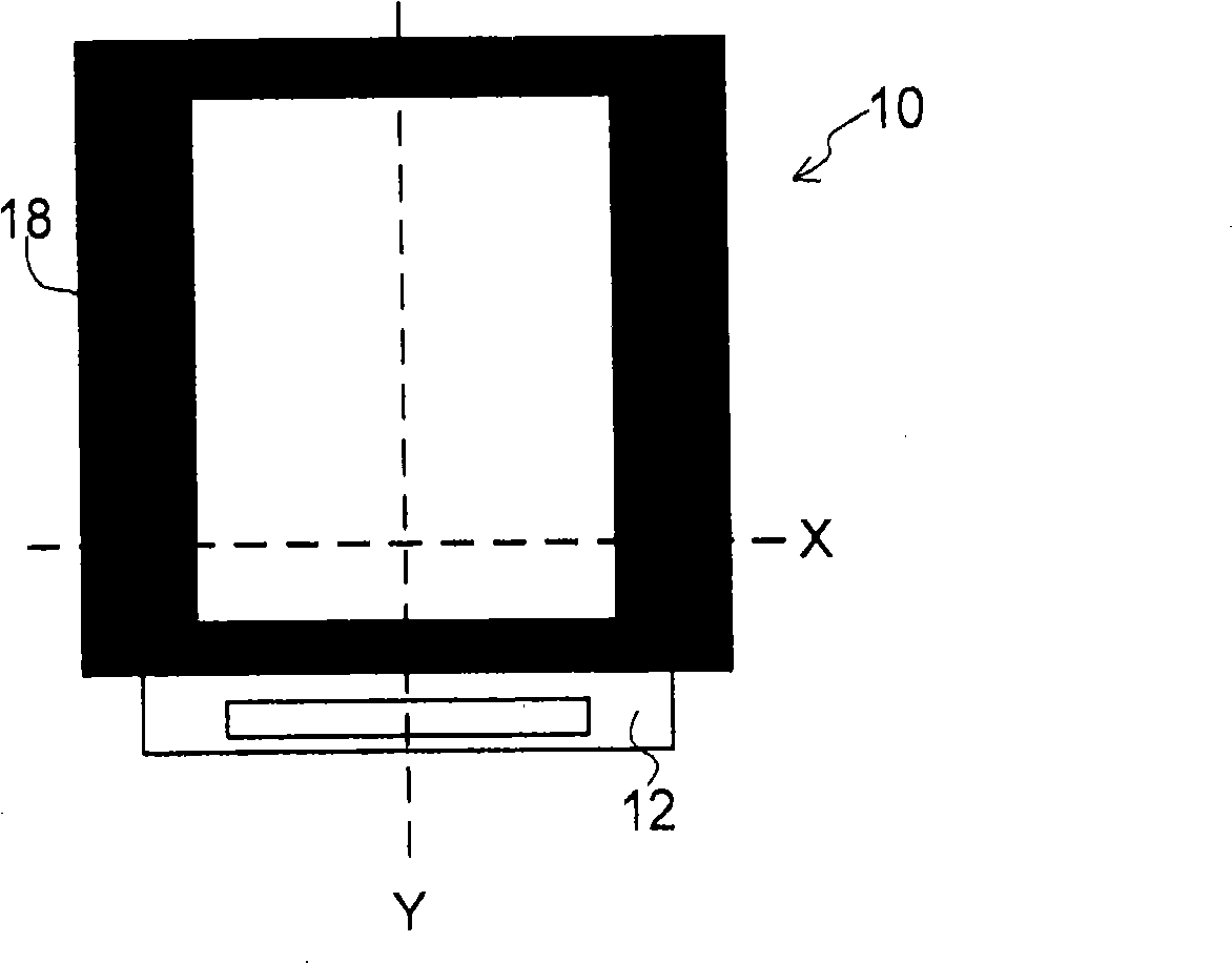
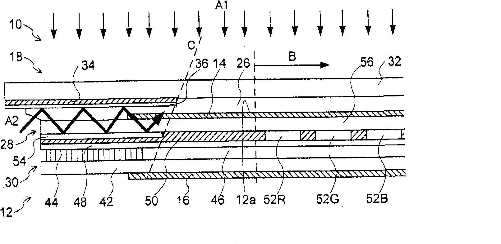
[0041] The display device of the present invention is provided with: a display panel having a display surface for displaying an image; a light-transmitting substrate facing the display surface; ; a light-curable light-transmitting adhesive for integrally bonding the display panel and the light-transmitting substrate; and a light-reflecting portion provided on the display surface side of the light-shielding portion. Accordingly, the light-transmitting adhesive constituting the light-shielding portion is in contact with the light-reflecting portion. Therefore, the light for curing the light-transmitting adhesive is prevented from being absorbed in the light-shielding portion, and the uncured portion of the light-transmitting adhesive in the light-shielding portion can be reduced.

[0042]Furthermore, a second light-shielding portion having light-shielding properties is also provided around the display panel, and a second reflection portion facing the light-shielding portion of t...


PUM


Abstract

In a case of curing and bonding a liquid crystal display panel (LCD) and a translucent substrate by using an optical adhesive, in order to reduce bonding fluctuations occurring in the vicinity of a light shielding portion provided on a periphery of the translucent substrate, enhance mechanical bonding strength, and prevent deterioration of image quality, which arises from curing variations of the optical adhesive, there is provided a display device including: a display panel including a display surface; a translucent substrate opposed to the display surface; a light shielding portion provided on a periphery of a display surface side of the translucent substrate, for shielding light; and a light reflecting portion provided on a display surface side of the light shielding portion.

Description

technical field [0001] The present invention relates to a display device using a display panel. In particular, it relates to a display device having a light-transmitting substrate structure in which a light-shielding portion is provided around a display surface side and attached to a display panel. Background technique [0002] Liquid crystal display devices (LC display devices) are used in various devices such as mobile phones, PDAs, electronic dictionaries, navigation systems, and music players. FIG. 6 shows a known conventional liquid crystal display device. Figure 6A is the floor plan, Figure 6B It is a longitudinal section view. As shown in the figure, the liquid crystal display device includes a liquid crystal display panel (LCD) 62 and a translucent substrate 68 serving as a front panel on the top thereof. In the LCD 62, a liquid crystal layer is sandwiched between two glass substrates, and polarizing plates are attached to the outer surfaces of the two glass sub...

Claims


Application Information

Patent Timeline
Patent Type & Authority Applications(China)
IPC IPC(8): G09F9/00G02F1/1333
CPCG02F2001/133388G02F1/133512G02F1/133388
Inventor 饭田治久
Owner SEIKO INSTR INC
Learn More