Radiating structure and use method thereof

A technology of heat dissipation structure and heat dissipation parts, applied in the direction of cooling/ventilation/heating transformation, electrical components, electric solid devices, etc., can solve the problems of difficult disassembly and assembly, long working hours, etc., and achieve the effect of easy fixing

Active Publication Date: 2009-08-19
ASUSTEK COMPUTER INC
View PDF0 Cites 13 Cited by
  • Summary
  • Abstract
  • Description
  • Claims
  • Application Information

AI Technical Summary

Problems solved by technology

Therefore, heat dissipation devices must be installed for each compone...

Method used


Image

  • Radiating structure and use method thereof
  • Radiating structure and use method thereof
  • Radiating structure and use method thereof

Examples


Embodiment Construction

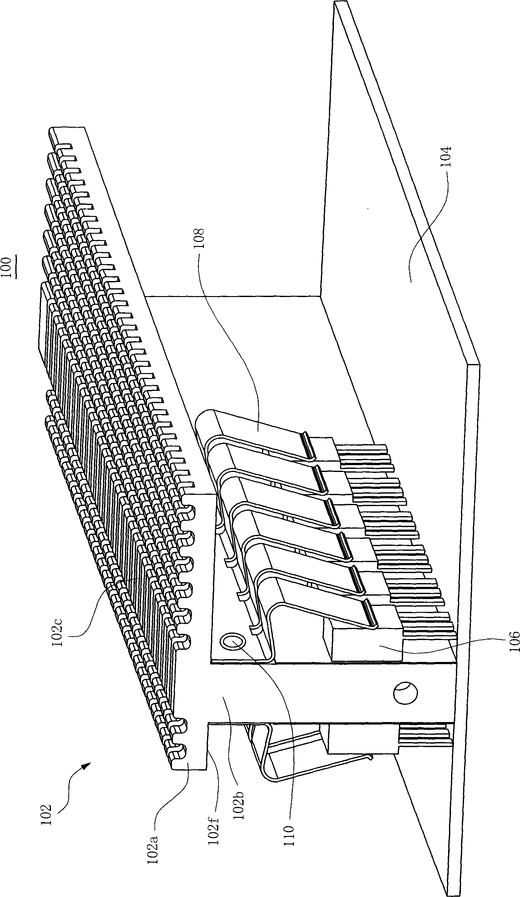
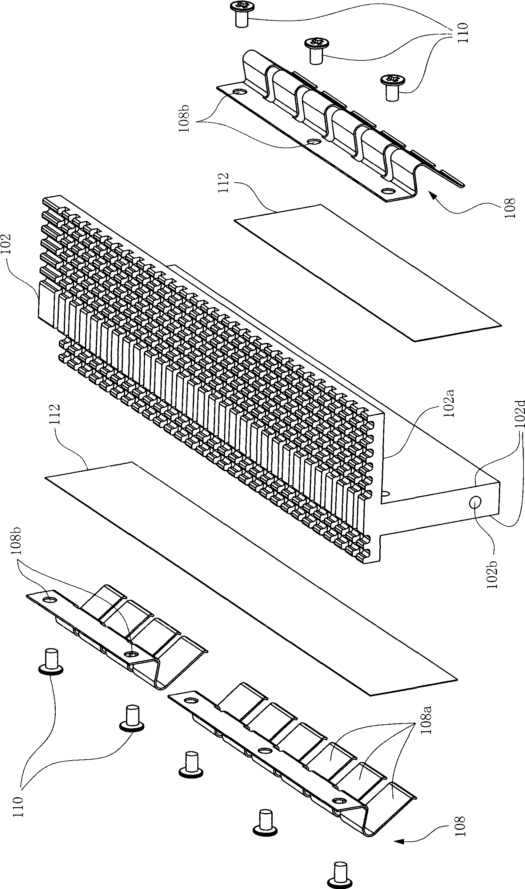
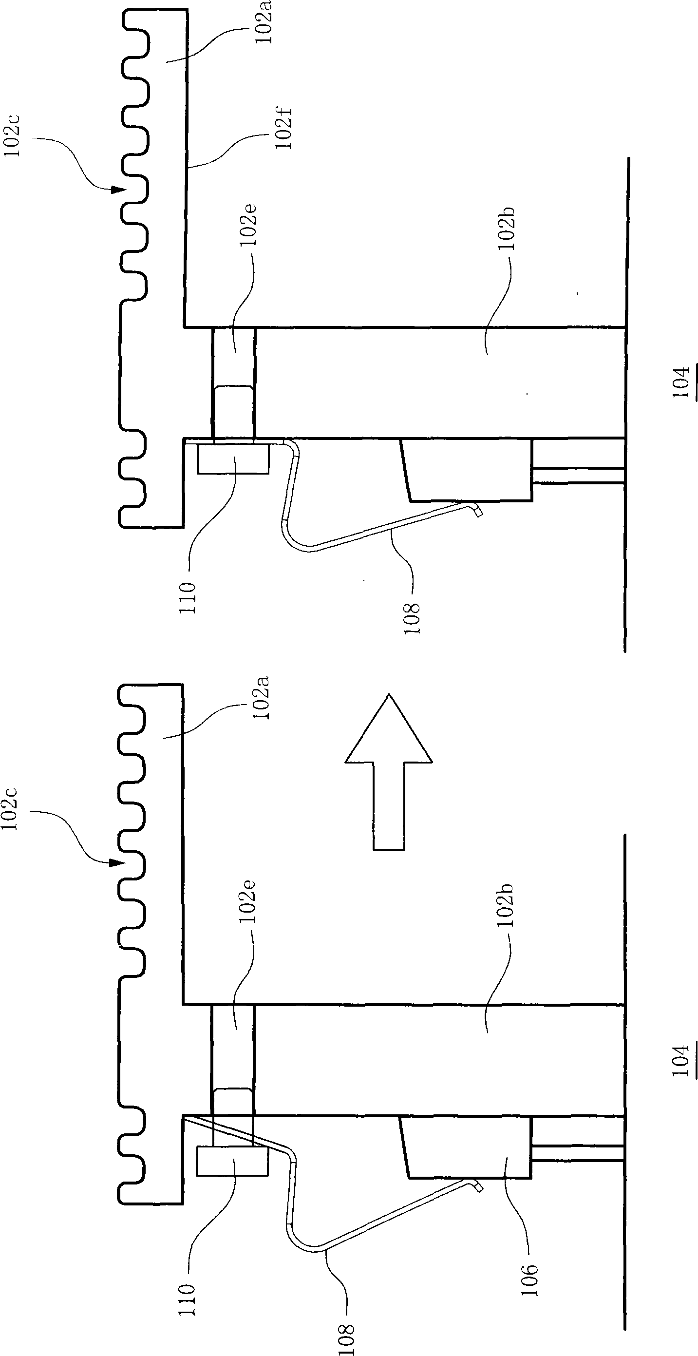
[0013] Please refer to figure 1 , shows a state in which a heat dissipation structure is mounted on a circuit board according to a preferred embodiment of the present invention. The circuit board 104 has two rows of right-angle transistors 106 (right-angle heating elements) upright connected to the circuit board. In order to increase the heat dissipation efficiency of the right-angle transistor 106 , a heat dissipation structure 100 is installed so that the heat generated by the right-angle transistor 106 can be conducted to the air more quickly. The heat dissipation structure 100 mainly includes a heat dissipation element 102 and a clamping portion 108 . The clamping portion 108 is locked on the support plate 102b by screws 110 . The heat sink 102 has a top plate 102a and a support plate 102b. The top surface of the top plate 102a is a heat dissipation surface 102c. The heat dissipation surface 102c is covered with protruding heat dissipation structures to increase the co...


PUM


Abstract

The invention provides a radiator structure which is used in a plurality of right-angle type heating element. The radiator structure includes a radiator piece and a clamping part. The radiator structure has a supporting plate. One end of the clamping part has a plurality of spring patches, anther end of the clamping part is fixed on the supporting plate, the spring patch clamp the right-angle type heating element for adhibiting the supporting plate.

Description

technical field [0001] The invention relates to a heat dissipation structure and its application method. Background technique [0002] Most of the known heat dissipation structures are suitable for components that lie flat (or flat) on the circuit board, but there is no good heat dissipation solution for some high-power components that stand upright (or vertical) on the circuit board. [0003] For example, right angle transistors often used in power amplifiers or power supplies, because the transistors generate a lot of heat when generating power consumption, poor heat dissipation of the transistors will reduce or damage the overall efficiency. A known solution is to provide a cooling device in conjunction with the transistor to reduce the temperature of the transistor, and the transistor needs to be in close contact with the cooling device to effectively conduct heat to the cooling fin. Such components are usually used in products that consume a large amount of power and n...

Claims


Application Information

Patent Timeline
IPC IPC(8): H05K7/20H01L23/34H01L23/367H01L23/40
Inventor 林琮凯陈永真
Owner ASUSTEK COMPUTER INC
Why Eureka
Try Eureka