Engine water pump leakage detecting device

An engine and water pump technology, applied in the field of engine water pump leak detection devices, can solve the problems of increasing the difficulty of engine sealing performance detection, unable to accurately display the location of leakage, affecting engine assembly efficiency, etc., and achieve accurate and reliable detection results. and reliable, reducing the workload of workers

Inactive Publication Date: 2010-10-06
力帆科技(集团)股份有限公司
View PDF5 Cites 0 Cited by
  • Summary
  • Abstract
  • Description
  • Claims
  • Application Information

AI Technical Summary

Problems solved by technology

Using an air tightness detector to detect is not only expensive, an air tightness detector costs tens of thousands of yuan, but also takes a long time to detect and the results are not accurate
Because the air tightness tester can only show that there is a leak in the engine, but cannot accurately show the location of the leak. If the water pump is not well sealed, the tester needs to check repeatedly to make a final determination. The check takes a long time and the workload is heavy.
It can be seen that if the water pump is not inspected separately when it enters the factory, it will not only result in lax quality control, lead to unnecessary troubles such as repeated assembly, affect the assembly efficiency of the engine and increase the workload of the workers, but also increase the quality of the engine. The difficulty of sealing performance testing

Method used


Image

  • Engine water pump leakage detecting device
  • Engine water pump leakage detecting device
  • Engine water pump leakage detecting device

Examples


Embodiment Construction

[0017] The present invention will be further described below in conjunction with the drawings and embodiments:

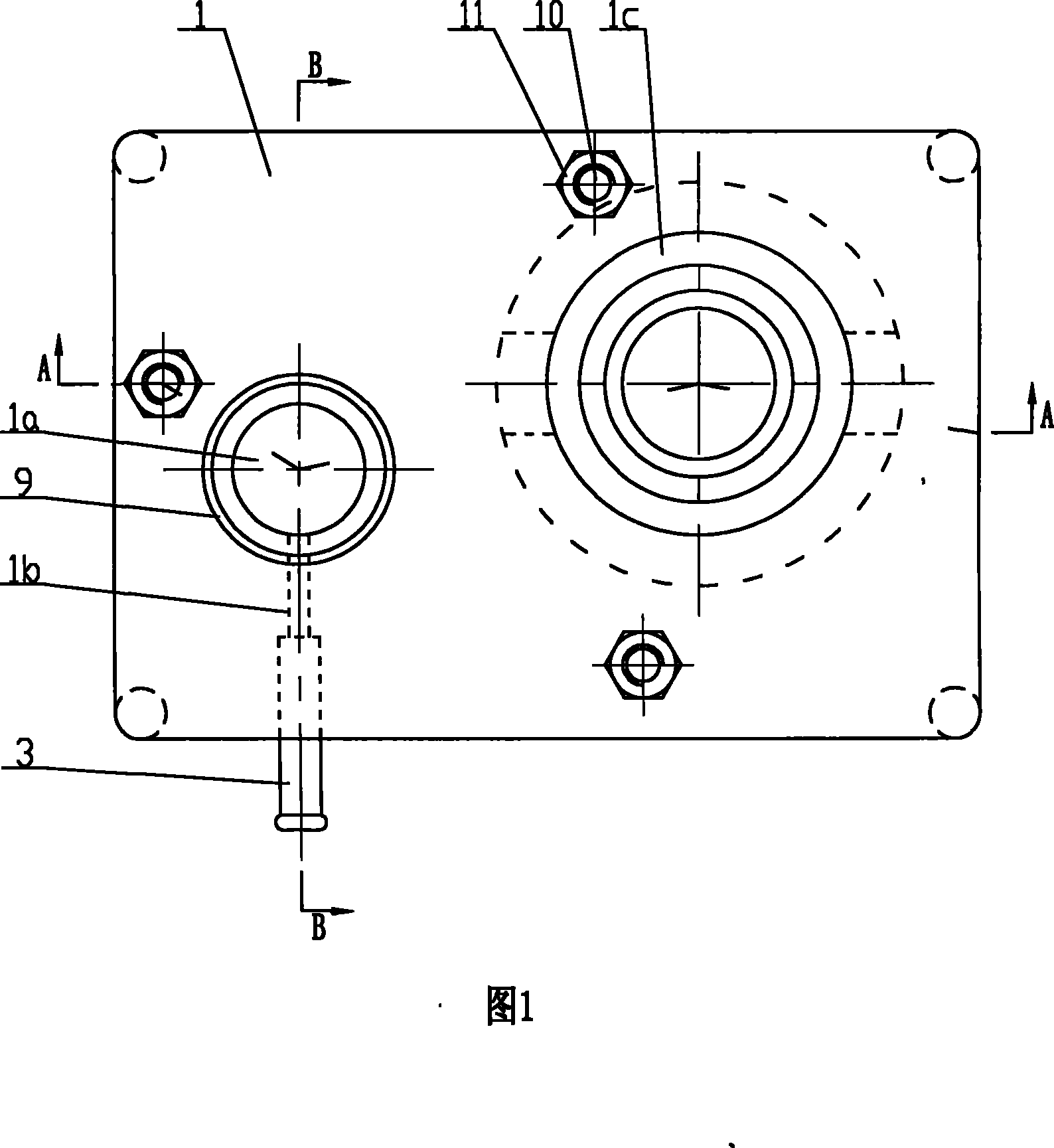
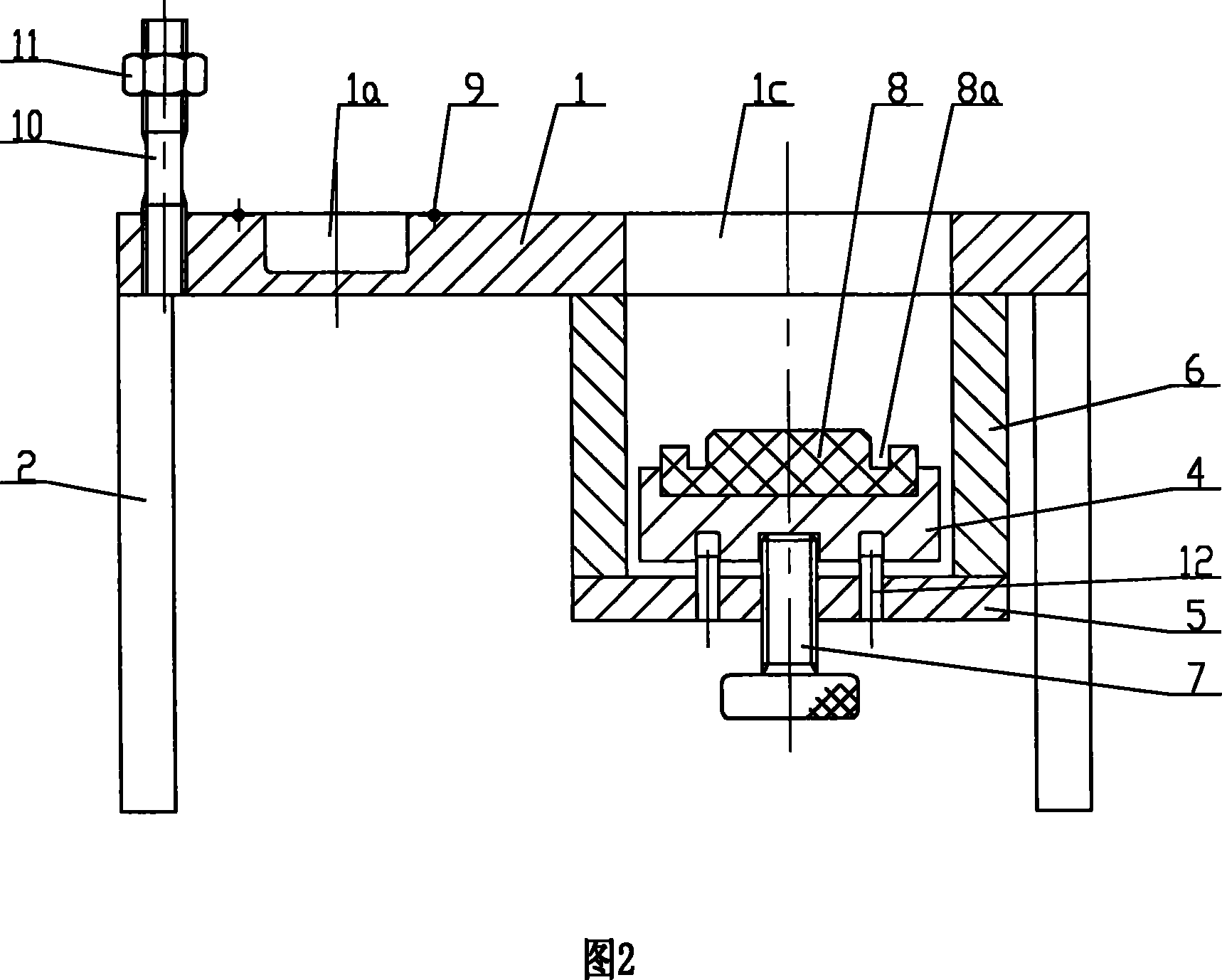
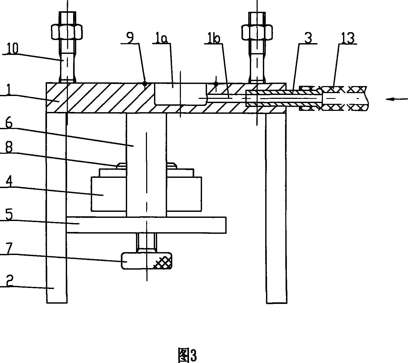
[0018] Such as figure 1 , figure 2 with image 3 As shown, the support platform 1 has a rectangular flat structure, and the four corners are supported by the uprights 2. Three stud bolts 10 distributed in a triangle are installed on the support table 1. The three stud bolts 10 correspond to the three mounting holes of the side water pump. The axis of each stud bolt 10 is perpendicular to the plate surface of the support table 1. The lower end of the bolt 10 is threaded with the support 1 (with threaded fastening glue), and a nut 11 is sleeved on the upper end of the stud bolt 10. A circular deep groove 1a, an annular shallow groove and an air inlet channel 1b are opened on the left part of the support platform 1, wherein the open end of the deep groove 1a is located on the upper surface of the support platform 1. The position and shape of the deep groove 1a And the s...


PUM


Abstract

The invention relates to an engine water pump leakage detecting device. A supporting table is provided with a deep groove and an air inlet passage, wherein an open end of the deep groove is positioned on the upper surface of the supporting table; an outlet of the air inlet passage is communicated with the deep groove; and an inlet of the air inlet passage is communicated to the end face of the supporting table, and is provided with an air pipe joint. The supporting table is also provided with a through hole which is used for a water inlet pipe of a water pump to be detected to pass through, and the right lower side of the through hole is provided with a positioning seat and a transverse plate, wherein the transverse plate is fixedly connected with the supporting table through a vertical beam. A bolt passes through the transverse plate from the bottom up and is connected with the bottom of the positioning seat, and the top of the positioning seat is provided with a sealing ring. The engine water pump leakage detecting device can independently detect the sealing performance of a water pump, strictly control the incoming quality of the water pumps, avoid unnecessary troubles of repeated assembly, and the like, effectively reduce the workload of workers, and improve the assembly efficiency of the engine. The engine water pump leakage detecting device also can reduce examination points of the sealing detection of the engine, and not only reduce the difficulty of the sealing detection of the engine, but also improve the efficiency of the sealing detection of the engine.

Description

Technical field [0001] The invention relates to an engine water pump leakage detection device, which is used for detecting the sealing performance of an automobile engine water pump. Background technique [0002] "Three leaks" (water leakage, oil leakage, air leakage) are common problems in engines. As an important part of the automobile engine, the water pump pressurizes the coolant to ensure the circulating flow of the coolant in the cooling system. The sealing performance of the water pump is directly related to the cooling effect of the engine. If the water pump leaks, the pressure of the entire water cooling circulation system will be insufficient, thereby reducing the flow rate of the coolant, and greatly affecting the cooling effect of the engine. In addition, users have to frequently add coolant, which is not only troublesome, but also increases the cost of use. [0003] At present, all automobile manufacturers use outsourcing water pumps to install directly on the engine...

Claims


Application Information

Patent Timeline
Patent Type & Authority Patents(China)
IPC IPC(8): G01M3/06G01M15/00
Inventor 张志发
Owner 力帆科技(集团)股份有限公司
Why Eureka
Try Eureka