Dual-band bandpass resonator and dual-band bandpass filter
A pass-through resonator, dual-band technology, applied to resonators, waveguide devices, circuits, etc., can solve the problems of insufficient and complete filtering of signals, unfavorable filter miniaturization, design of dual-band band-pass filters, etc., to achieve small effect
- Summary
- Abstract
- Description
- Claims
- Application Information
AI Technical Summary
Problems solved by technology
Method used
Image
Examples
no. 1 Embodiment approach
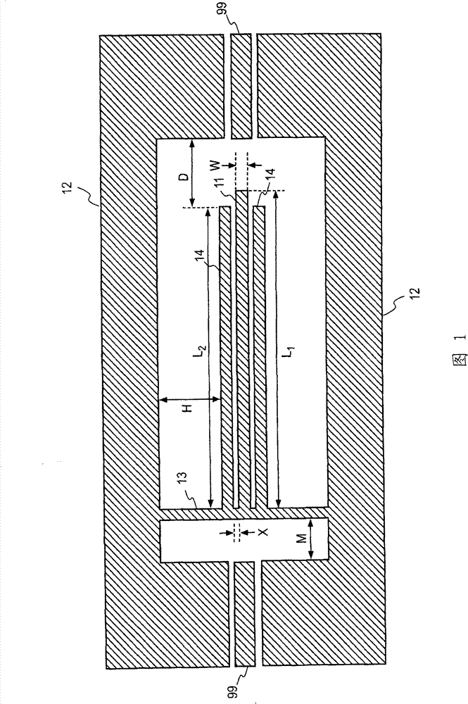
[0073] FIG. 1 is a structural example of a dual-band bandpass resonator according to the present invention. The resonator is formed by forming a conductive pattern on one surface of a rectangular dielectric substrate. In addition, conductors exist in hatched areas in the figure, and areas without hatching surrounded by hatched areas represent portions where the dielectric substrate under the conductors is exposed. This description is the same for all the following drawings showing resonators and filters.
[0074] The dual-band bandpass resonator is composed of a center conductor 11 , a set of ground conductors 12 , a center conductor short-circuit portion 13 , and a set of stub conductors 14 . One set of ground conductors is formed at intervals along one set of two opposing sides of the rectangular dielectric substrate, and both ends thereof extend at right angles along the other set of opposing sides of the dielectric substrate so as to approach each other. The input and out...
no. 2 Embodiment approach
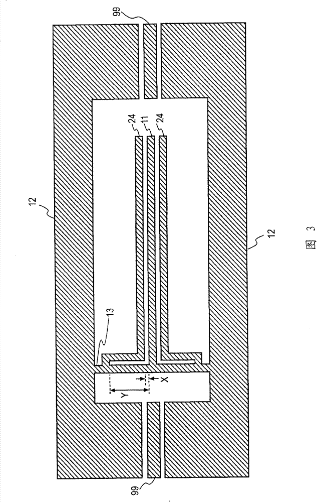
[0081] FIG. 3 shows a second embodiment of the dual-band bandpass resonator of the present invention.
[0082] The dual-frequency bandpass resonator in FIG. 3 is composed of a central conductor 11 , a set of ground conductors 12 , a short-circuit portion 13 of the central conductor, and a set of stub conductors 24 . All other than the stub conductor 24 are the same as the configuration of the first embodiment ( FIG. 1 ), so the same reference numerals are assigned and descriptions are basically omitted. The same applies to the following embodiments.
[0083] The stub conductors 14 of the first embodiment are arranged so that their entire lengths are parallel to the center conductor 11, but the pair of stub conductors 24 of the second embodiment pass most of the center conductor 11 from the beginning as shown in FIG. 3 . The conductors 11 are parallel, but are bent at approximately right angles to the direction of the ground conductor 12 in the vicinity of the center conductor...
no. 3 Embodiment approach
[0086] FIG. 4 shows a third embodiment of the dual-band bandpass resonator of the present invention.
[0087] The dual-frequency bandpass resonator in FIG. 4 is composed of a center conductor 11 , a set of ground conductors 12 , a center conductor short-circuit portion 13 , and a set of stub conductors 34 . The only difference from the first and second embodiments is the stub conductor 34 .
[0088] In the stub conductor 24 of the second embodiment, most of its longitudinal direction is parallel to the central conductor 11, but it bends toward the ground conductor 12 in the vicinity of the central conductor short-circuit portion 13, and then bends toward the ground conductor 12 in front of the ground conductor 12 again. The central conductor short-circuit portion 13 is bent in a direction and connected to the central conductor short-circuit portion 13 . By making the connection position with the center conductor short-circuit portion 13 close to the ground conductor 12, the l...
PUM
 Abstract
Description
Claims
Application Information
 - R&D
- Intellectual Property
- Life Sciences
- Materials
- Tech Scout
- Unparalleled Data Quality
- Higher Quality Content
- 60% Fewer Hallucinations
Browse by: Latest US Patents, China's latest patents, Technical Efficacy Thesaurus, Application Domain, Technology Topic, Popular Technical Reports.
© 2025 PatSnap. All rights reserved.Legal|Privacy policy|Modern Slavery Act Transparency Statement|Sitemap|About US| Contact US: help@patsnap.com


